Hi Robin,
Could you please recommend a voltage regulator IC (or circuit?) that would be suitable for powering the STM32-H103 (3.3V) from an automotive 12V?
Thanks again for all the help/advice so far
cheers
ali
help with microcontroller/electrical interfacing
Re: help with microcontroller/electrical interfacing
Or how about http://uk.farnell.com/national-semicond ... dp/9489800 ? It looks a lot simpler to use, and can handle an input range of 6.5V-40V?
Thanks
ali
Thanks
ali

Re: help with microcontroller/electrical interfacing
HI Ali,
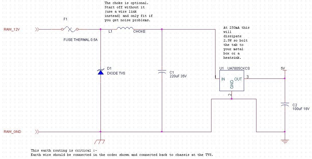
Farnell is offline right now so cannot check out those parts, however I would suggest you put in layers of protection in the form of the schematic below. I'll post some probable part numbers once Farnell is back on line.
Fuse F1 limits current into the circuit and is a thermal resettable fuse.
TVS (transient voltage suppressor) D1 should have a holding (=working) voltage of 16V with a clamping voltage of ~20V. It will then shunt any voltages above 20V back out the ground return wire - if there is a sustained over voltage condition F1 will "blow".
Choke L1 can be replaced with a bit of wire until you know you need it Basically a choke with rating 1-5mH and 1A current rating will help filter out high frequency noise from the line if it turns out to couple through to your circuit in a way that matters. This is more likely to be a problem if you start trying to use the ADC to measure voltages rather than just switching on square waves.
Working voltage of C1 is 35V, comfortably above the 20V clamping voltage of the TVS (this allows some head room for working at higher temperatures). This should almost certainly be an aluminium electrolytic capacitor as anything else will be way too expensive and not any better.
Then the 5V linear regulator steps down the nominal 12-15V from your alternator to 5V.
Output capacitor C2 is required to make sure that the linear regulator remains stable - again an aluminium electrolytic is probably the best value for money here until you get space constrained.
You would then hook your 3.3V linear regulator off the back of the chunky 5V regulator.
Note the comments on earth wiring - it's important that the path RAW_12V -> FUSE -> TVS -> RAW_GND has a high current path that is as short as possible. Then it's important to make sure that the RAW_GND and digital GND connect together in just one place - which should be at the GND pin of the 5V linear regulator.
You could use a larger voltage linear regualator for the first stage - e.g. 8.0 volts - the point is just to provide a stable voltage to the next path.
If the 3.3V regulator is man enough to step down from 20V to 3.3V at your required current rating you could use it. Keep in mind power dissipation will be (15V-3.3V) * output current, e.g. 11.7V * 200mA = 2.34W - that might be more than your 3.3V device package can handle. I would generally produce a higher voltage in a bigger package, then step down to the final level in a smaller package.
Hope that makes some sense ...
Cheers,
Robin
Farnell is offline right now so cannot check out those parts, however I would suggest you put in layers of protection in the form of the schematic below. I'll post some probable part numbers once Farnell is back on line.
Fuse F1 limits current into the circuit and is a thermal resettable fuse.
TVS (transient voltage suppressor) D1 should have a holding (=working) voltage of 16V with a clamping voltage of ~20V. It will then shunt any voltages above 20V back out the ground return wire - if there is a sustained over voltage condition F1 will "blow".
Choke L1 can be replaced with a bit of wire until you know you need it
Working voltage of C1 is 35V, comfortably above the 20V clamping voltage of the TVS (this allows some head room for working at higher temperatures). This should almost certainly be an aluminium electrolytic capacitor as anything else will be way too expensive and not any better.
Then the 5V linear regulator steps down the nominal 12-15V from your alternator to 5V.
Output capacitor C2 is required to make sure that the linear regulator remains stable - again an aluminium electrolytic is probably the best value for money here until you get space constrained.
You would then hook your 3.3V linear regulator off the back of the chunky 5V regulator.
Note the comments on earth wiring - it's important that the path RAW_12V -> FUSE -> TVS -> RAW_GND has a high current path that is as short as possible. Then it's important to make sure that the RAW_GND and digital GND connect together in just one place - which should be at the GND pin of the 5V linear regulator.
You could use a larger voltage linear regualator for the first stage - e.g. 8.0 volts - the point is just to provide a stable voltage to the next path.
If the 3.3V regulator is man enough to step down from 20V to 3.3V at your required current rating you could use it. Keep in mind power dissipation will be (15V-3.3V) * output current, e.g. 11.7V * 200mA = 2.34W - that might be more than your 3.3V device package can handle. I would generally produce a higher voltage in a bigger package, then step down to the final level in a smaller package.
Hope that makes some sense ...
Cheers,
Robin
I is in your loomz nibblin ur wirez
#bemoretut
#bemoretut
Re: help with microcontroller/electrical interfacing
Rich,
(1) The easiest way to do what you want is without doubt with a microcontroller, so what follows below is for amusement, not actually the easiest way.
(2) Analog approach - I fancy a nearly pure analog implementation - hardest to get right, but somehow satisfying. However, that's really quite hard!
(3) Digital approach.
Input trigger circuit to tidy up the square wave - basically you need a schmitt trigger or equivalent to make sure you get just one rising edge per ignition event.
Feed this into a National Semiconductor LM331 Voltage to Frequency converter, but this is configured as a Frequency to Voltage converter instead (see the data sheet). This spews out a voltage that is directly proportional to pulse frequency and thus RPM. For maximum head room I would probably run this off a protected 12v supply - you cannot just run it off the +12 wire in the car Configure the converter to produce 0v at stall and 10v at 10,000 RPM.
Now you need a master clock running at, say 32768HZ - nice common crystal, clocking a 12-bit counter.
When bit 11 (most significant bit) is clear, the output of the LM331 is connected to a capacitor by virtue of an analog switch. Bit 11 is called HOLD_SAMPLE (i.e. hold when 1, sample when 0).
The capacitor is fed through a unity gain op-amp - the point of this is just to avoid draining the capacitor by the next stage. So when HOLD_SAMPLE goes high, the output of the op-amp should remain relatively stable. Note that at 32768Hz, HOLD_SAMPLE will toggle 32 times a second.
So when HOLD_SAMPLE goes high, the output of the op-amp is connected to the inverting input of a second op-amp via an analog switch; previously the input was connected to ground, perhaps via a pull-down resistor.
The non-inverting input of this second op-amp is connected to a ramp generator that is released by the rising edge of HOLD_SAMPLE. The slope of the ramp generator should be such that it goes from 0 to 10v in 200 cycles of the 32768 clock (clearly you could produce the ramp digitally with a DAC driven by the low order outputs of the counter). Note that the ramp output should be at a >0 voltage while HOLD_SAMPLE is low.
The output of this second op-amp will be low while the sampled voltage is higher than the ramp output and will go high as soon as the ramp output is higher than the sampled voltage.
Feed the output of this op-amp into one input of a two-input NAND gate.
Feed the 32768 clock into the other input of this two-input NAND gate.
The output of the NAND gate will then be the clock while the ramp is rising up to the target voltage, or while the HOLD_SAMPLE is low (because the comparator op-amp will have it's inverting terminal grounded in this case while the ramp output is always >0).
Now you need an array of shift registers. Assuming we want to count in resolution of 10RPM and we want three managed Nixies (i.e. 0000 to 9990) then we need three 10-bit shift registers with carry in (bit 0 to bit 9). For the units digit, I guess you just hardwire the 0-cathode to on.
Wire the resets of all three shift registers to HOLD_SAMPLE. Assuming active low reset, that means the shift registers will all be held in reset while HOLD_SAMPLE is low.
Now we need to lash up a way of preloading each shift register with bit0=1, bit1...9=0 as well as feeding back bit 9 to carry in - it's easy enough to do with a few XOR gates and flip flops, just tedious to explain
Now if you clock the first shift register with the output of the NAND gate, the second one with bit 9 of the first and the third one with bit 9 of the second, hopefully you can see how the three shift registers will clock through from 000 to 999.
Finally you need to put in a 30-bit latch to latch the outputs of the shift register on the next falling edge of HOLD_SAMPLE - the outputs of this latch are (logically, at least) the cathode drivers ...
Easy, eh?
I reckon you could learn C more easily ....
Cheers,
Robin
(1) The easiest way to do what you want is without doubt with a microcontroller, so what follows below is for amusement, not actually the easiest way.
(2) Analog approach - I fancy a nearly pure analog implementation - hardest to get right, but somehow satisfying. However, that's really quite hard!
(3) Digital approach.
Input trigger circuit to tidy up the square wave - basically you need a schmitt trigger or equivalent to make sure you get just one rising edge per ignition event.
Feed this into a National Semiconductor LM331 Voltage to Frequency converter, but this is configured as a Frequency to Voltage converter instead (see the data sheet). This spews out a voltage that is directly proportional to pulse frequency and thus RPM. For maximum head room I would probably run this off a protected 12v supply - you cannot just run it off the +12 wire in the car
Now you need a master clock running at, say 32768HZ - nice common crystal, clocking a 12-bit counter.
When bit 11 (most significant bit) is clear, the output of the LM331 is connected to a capacitor by virtue of an analog switch. Bit 11 is called HOLD_SAMPLE (i.e. hold when 1, sample when 0).
The capacitor is fed through a unity gain op-amp - the point of this is just to avoid draining the capacitor by the next stage. So when HOLD_SAMPLE goes high, the output of the op-amp should remain relatively stable. Note that at 32768Hz, HOLD_SAMPLE will toggle 32 times a second.
So when HOLD_SAMPLE goes high, the output of the op-amp is connected to the inverting input of a second op-amp via an analog switch; previously the input was connected to ground, perhaps via a pull-down resistor.
The non-inverting input of this second op-amp is connected to a ramp generator that is released by the rising edge of HOLD_SAMPLE. The slope of the ramp generator should be such that it goes from 0 to 10v in 200 cycles of the 32768 clock (clearly you could produce the ramp digitally with a DAC driven by the low order outputs of the counter). Note that the ramp output should be at a >0 voltage while HOLD_SAMPLE is low.
The output of this second op-amp will be low while the sampled voltage is higher than the ramp output and will go high as soon as the ramp output is higher than the sampled voltage.
Feed the output of this op-amp into one input of a two-input NAND gate.
Feed the 32768 clock into the other input of this two-input NAND gate.
The output of the NAND gate will then be the clock while the ramp is rising up to the target voltage, or while the HOLD_SAMPLE is low (because the comparator op-amp will have it's inverting terminal grounded in this case while the ramp output is always >0).
Now you need an array of shift registers. Assuming we want to count in resolution of 10RPM and we want three managed Nixies (i.e. 0000 to 9990) then we need three 10-bit shift registers with carry in (bit 0 to bit 9). For the units digit, I guess you just hardwire the 0-cathode to on.
Wire the resets of all three shift registers to HOLD_SAMPLE. Assuming active low reset, that means the shift registers will all be held in reset while HOLD_SAMPLE is low.
Now we need to lash up a way of preloading each shift register with bit0=1, bit1...9=0 as well as feeding back bit 9 to carry in - it's easy enough to do with a few XOR gates and flip flops, just tedious to explain
Now if you clock the first shift register with the output of the NAND gate, the second one with bit 9 of the first and the third one with bit 9 of the second, hopefully you can see how the three shift registers will clock through from 000 to 999.
Finally you need to put in a 30-bit latch to latch the outputs of the shift register on the next falling edge of HOLD_SAMPLE - the outputs of this latch are (logically, at least) the cathode drivers ...
Easy, eh?
I reckon you could learn C more easily ....
Cheers,
Robin
I is in your loomz nibblin ur wirez
#bemoretut
#bemoretut
Re: help with microcontroller/electrical interfacing
P.S. Ali, I note that those parts appear to be switch mode regulators (looking at their URLs). No way would I bother with that for something that's driven in a car ... linear regulators are much less efficient but trivial to implement and are what the ECU designers appear to use
Cheers,
Robin
Cheers,
Robin
I is in your loomz nibblin ur wirez
#bemoretut
#bemoretut

Re: help with microcontroller/electrical interfacing
I think I follow: count for a time until the sample freq voltage matches the calibrated ramp voltage then display, freeze and reset.
I'll have a look
C sound easier
Ta
Rich
I'll have a look
C sound easier
Ta
Rich
1994 Lotus Esprit S4 - Work in progress
1980 Porsche 924 Turbo - Funky Interior Spec
2004 Smart Roadster Coupe - Hers
1980 Porsche 924 Turbo - Funky Interior Spec
2004 Smart Roadster Coupe - Hers
Re: help with microcontroller/electrical interfacing
I have a better plan involving three DACS and three ramps and three 10-segment bar LED drivers ... will post something about it tonight - I reckon it will be simpler.
Cheers,
Robin
Cheers,
Robin
I is in your loomz nibblin ur wirez
#bemoretut
#bemoretut
Re: help with microcontroller/electrical interfacing
Trouble I had witht eh bar graph drivers is keeping the units counting, they are built to just add on to each other.
Its what I have running the AFR meter in the Porker. Those LED gauges are a rip off, a couple of resistors, a few LEDs and a single IC!
But I've no doubt you have that under control!
1994 Lotus Esprit S4 - Work in progress
1980 Porsche 924 Turbo - Funky Interior Spec
2004 Smart Roadster Coupe - Hers
1980 Porsche 924 Turbo - Funky Interior Spec
2004 Smart Roadster Coupe - Hers
Re: help with microcontroller/electrical interfacing
Yes, hence the three ramps - each ramp feeds on digit of the bar graph (which is really feeding the Nixie) ...
I is in your loomz nibblin ur wirez
#bemoretut
#bemoretut
Re: help with microcontroller/electrical interfacing
All these in stock on Farnell for pennies; farnell order code in brackets:
F1, e.g. BOURNS MF-R110-0-99 (9350462)
D1, e.g. MULTICOMP SA16A (1578906)
L1, no fit for now, replace with wire.
C1, e.g. MULTICOMP MCGPR35V227M10X13 (9451293)
C2, e.g. MULTICOMP MHR16V107M6.3X7. (3017590)
U1, e.g. FAIRCHILD SEMICONDUCTOR KA7805AETU (1564483)
Note, you can replace U1 with 78xx where xx is 08,10,12 depending on the first stage regulated voltage you choose to use - I would stick with an 05 unless you know you need some higher voltage for another function.
For second stage voltage, to produce 3.3V I would add:
ON SEMICONDUCTOR NCP1117DT33RKG (1652365)
Note that although this is a surface mount package, it has sturdy legs with reasonable spacing and you will be able to solder to the solder side of normal strip board without any trouble.
For simplicity I would place a third capacitor on the output of this part, 100uF with a 6v working voltage (though you can just use the 16v one listed above - it'll work just as well).
Take care to design your layout on a bit of paper before wading in - if you've done a good job on the design, you can precut all the strips at the relevant places and then just solder all the parts on.
Cheers,
Robin
I is in your loomz nibblin ur wirez
#bemoretut
#bemoretut
Re: help with microcontroller/electrical interfacing
Rather than the solder the IC in place then work it out like I tend to 
1994 Lotus Esprit S4 - Work in progress
1980 Porsche 924 Turbo - Funky Interior Spec
2004 Smart Roadster Coupe - Hers
1980 Porsche 924 Turbo - Funky Interior Spec
2004 Smart Roadster Coupe - Hers
Re: help with microcontroller/electrical interfacing
That's fantastic - thanks again
Cheers
ali
Cheers
ali
Re: help with microcontroller/electrical interfacing
Sorry to be a pain but I'm putting my shopping basket of bits together on farnell and think I have everything I need except the schottky diodes for the trigger circuit - could you possibly suggest a suitable part, or let me know the crucial specifications I need to look out for on it? I'm rather lost looking at the array of options!
Thanks again.
ali
Thanks again.
ali
Re: help with microcontroller/electrical interfacing
I'm visiting Farnell trade counter tomorrow, their depot is in Preston 
1994 Lotus Esprit S4 - Work in progress
1980 Porsche 924 Turbo - Funky Interior Spec
2004 Smart Roadster Coupe - Hers
1980 Porsche 924 Turbo - Funky Interior Spec
2004 Smart Roadster Coupe - Hers