PICs are crap

I tend to avoid them because of their byzantine programming model. That said, if you have one that you're comfortable writing code for, I'm sure it will do the job. These days embedded ARM7 is so cheap and versatile, I don't understand why people would use anything else (though if you want an 8-bit MCU, Atmel's AVR are so much simpler than the PIC).
On the elise the tacho signal to the dash is synthesized by the ECU (i.e. it is not the LT coil feed, thankfully). It's nominally a 12v square wave, but actually at higher RPM it probably won't make 12v and the rising edges are going to be exponential rather than properly square. However, if you cut it off at about 3v and ignore the shape above, it will be square at any RPM.
You don't need a zener (not zenier) diode to filter the pulses.
A high impedance input to a schmitt triggered buffer (or, if you prefer, you can make such a thing with a clever organisation of a couple of NPN transistors) is more than adequate to convert the input 0..12v signal into a logic level square wave.
What sort of construction are you looking for - presumably you're happy with soldering circuits in vero boards?
The most straight forward way of doing this would be:
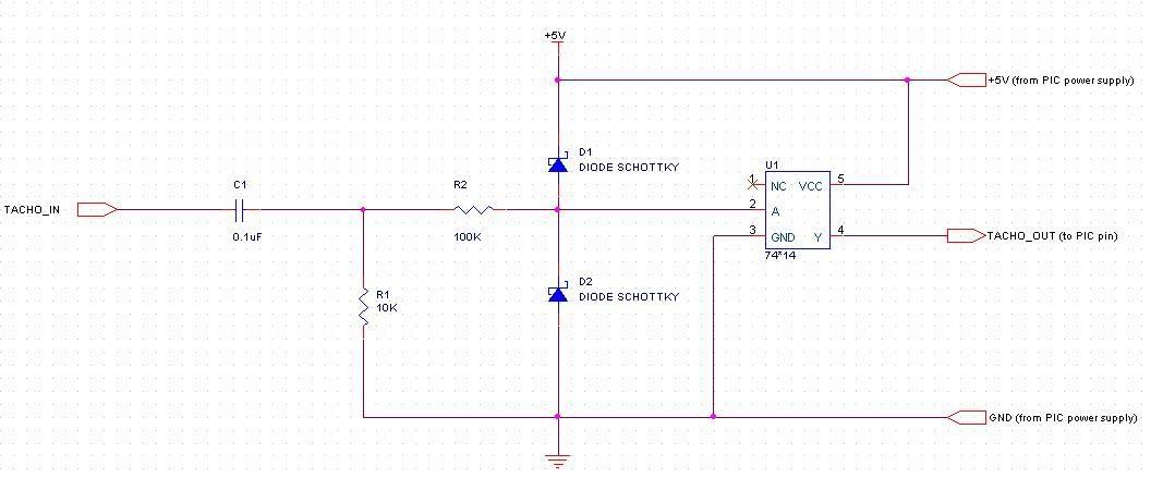
input -> 10K..1M ohm resistor (use highest value that works) -> 7414 schmitt trigger invertor -> PIC input pin (then count or time the pulses in s/w to do whatever it is you want)
Now, you also need to put a schottky diode after the input resistor to the 7414 power supply and another one down to the 0v. The point is to shunt any voltage above the power supply level into the power supply and anything below 0 into the ground rail - this is just there to protect the schmitt trigger - it's common practice in automotive electronics to protect inputs like this, because you see ludicrous spikes and troughs from time to time (think +/- 50v).
You can further protect your circuit by sticking a 0.1uF 50v non-polarised capacitor in series with the input (i.e. before the resistor) and then a resistor with 10x the resistance of the series resistor to ground. The series capacitor will block any DC (and thus prevent your circuit becoming an accidental path to ground for any stray high voltages). The high value resistor makes sure the input signal remains more-or-less grounded when not being stimulated (otherwise you may get noise triggering the circuit while the ECU is powered off).
(I'll draw a schematic later and post it up).
You can replace the 7414 with any schmitt triggered buffer that you can get, for example, the TI SN74AUC1G17DBVR or Fairchild Semiconductor NC7WZ17P6X are both low cost single or dual schmitt triggered buffers in surface mount packages.
Cheers,
Robin