Duratec in detail

Re: Duratec in detail
Love the attention to detail, in an effort to come as close to perfection as possible. Will be watching with interest.

1999 S1 Elise 111S - Fun Spec
2004 Mercedes Benz CLK 200 - Daily Driver Spec
2004 Mitsubishi Shogun- Dog Transport Spec

Re: Duratec in detail
I'm still waiting for the crank to be returned and a load of bits, but here's an up date of some of the learning process i going through with the Duratec . . .
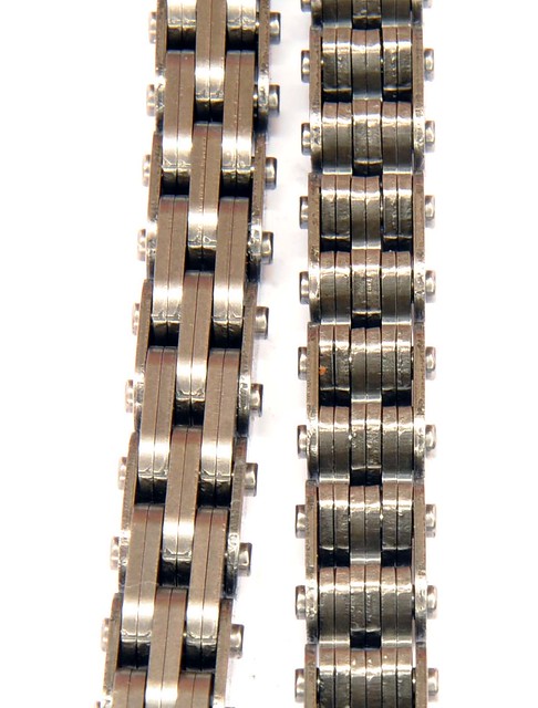
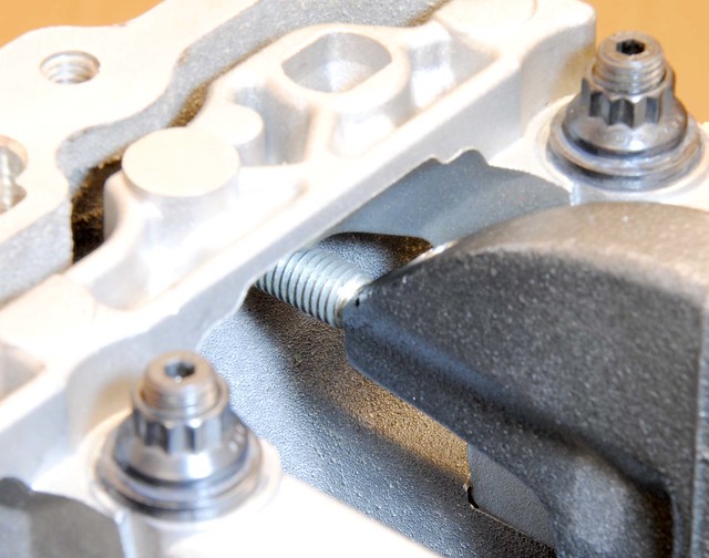
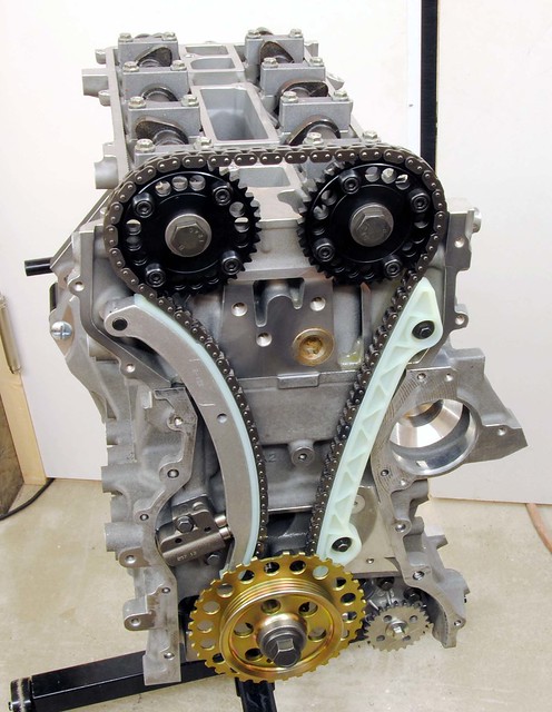
DOHC engines tend to have cam belts as they provided a easy solution to the longer runs and high RPM. But with higher production costs to keep the belt clear of oil, it was only a matter of time before the chains made a comeback. The Duratec uses an eight segment design, and, unlike a conventional chains, the segments engage directly with the sprocket. Typical of this engine, it is a clever low cost solution.
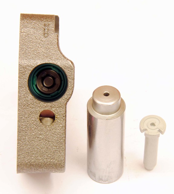
Following on from the chain, the standard tensioner (bottom in the picture) is spring loaded device that also utilises oil pressure. There is a spring ratchet mechanism that takes up the slack when the engine is not running and a small hole in the nose that squirts oil onto the chain (through a hole in the guide).
Before I had the dry sump, I lost oil pressure on my R400 and there was a terrifying noise - not a knock like you might expect from bearings, but more like a 'bag of spanners'. I suspect the ratchet mechanism was defeated and the chain lost tension. I got away with it on the ‘standard’ engine but that might not be the case with hotter cams and higher CR piston.
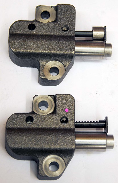
The solution is a modified tensioner (top picture) - there are variations on the theme, but basically a mechanical stop is added to limit how slack the chain can get. This one also has the ratchet machined off completely.
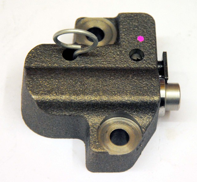
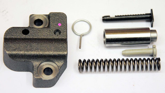
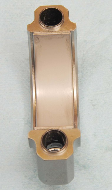
Here's a picture of the tensioner showing the internal valve. The valve inside appears to be 'on-way' and, using the spring, regulates oil flow when pressure is low. Because the spring acts to both tension the chain and regulate the oil pressure, the spring tension will be replaced (and not added to) when oil pressure is sufficient. Also, as the piston would be full of oil with the only exit via the small hole in the tip (non-return valve the other end), it will act as a damper and help keeps the tension guide in contact with the chain.
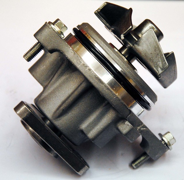
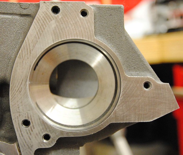
The water pump is a conventional set-up. The cone shape impeller fits in a cone shape that has been machined in the block - coolant being sucked into the centre and thrown out to a ring in the housing - not unlike a turbo charger in appearance. The coolant exiting from the pump is split in two - one flow being directed to each side of the block for even cooling. On a high RPM engine it will cavitate, so steps need to be taken to slow it down and this can be done with either with a larger pulley on the pump or a smaller one on the crank.
The thermostat is 'conventional' (that's a word that I'm using a lot on this engine) but, as is often the case with the Duratec, there's usually a twist to the design. . .
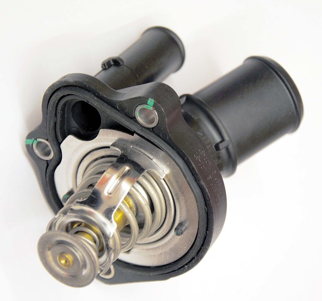
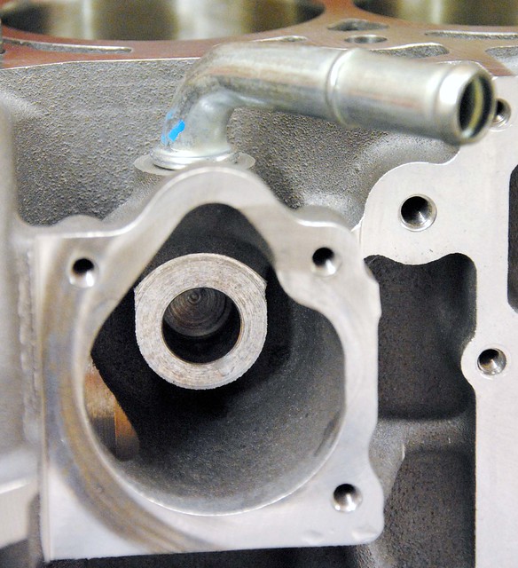
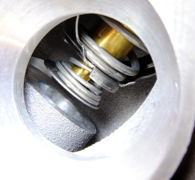
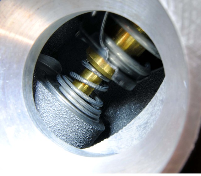
The thermostat housing has a re-circulation pipe that allows for coolant to circulate around the block when the thermostat is closed. The thermostat is, in fact, a two-way valve and blocks off the re-circulation pipe when it opens. The bottom picture shows the thermostat after being heated up in boiling water. This engine will use a 82 degree thermostat.
DOHC engines tend to have cam belts as they provided a easy solution to the longer runs and high RPM. But with higher production costs to keep the belt clear of oil, it was only a matter of time before the chains made a comeback. The Duratec uses an eight segment design, and, unlike a conventional chains, the segments engage directly with the sprocket. Typical of this engine, it is a clever low cost solution.
Following on from the chain, the standard tensioner (bottom in the picture) is spring loaded device that also utilises oil pressure. There is a spring ratchet mechanism that takes up the slack when the engine is not running and a small hole in the nose that squirts oil onto the chain (through a hole in the guide).
Before I had the dry sump, I lost oil pressure on my R400 and there was a terrifying noise - not a knock like you might expect from bearings, but more like a 'bag of spanners'. I suspect the ratchet mechanism was defeated and the chain lost tension. I got away with it on the ‘standard’ engine but that might not be the case with hotter cams and higher CR piston.
The solution is a modified tensioner (top picture) - there are variations on the theme, but basically a mechanical stop is added to limit how slack the chain can get. This one also has the ratchet machined off completely.
Here's a picture of the tensioner showing the internal valve. The valve inside appears to be 'on-way' and, using the spring, regulates oil flow when pressure is low. Because the spring acts to both tension the chain and regulate the oil pressure, the spring tension will be replaced (and not added to) when oil pressure is sufficient. Also, as the piston would be full of oil with the only exit via the small hole in the tip (non-return valve the other end), it will act as a damper and help keeps the tension guide in contact with the chain.
The water pump is a conventional set-up. The cone shape impeller fits in a cone shape that has been machined in the block - coolant being sucked into the centre and thrown out to a ring in the housing - not unlike a turbo charger in appearance. The coolant exiting from the pump is split in two - one flow being directed to each side of the block for even cooling. On a high RPM engine it will cavitate, so steps need to be taken to slow it down and this can be done with either with a larger pulley on the pump or a smaller one on the crank.
The thermostat is 'conventional' (that's a word that I'm using a lot on this engine) but, as is often the case with the Duratec, there's usually a twist to the design. . .
The thermostat housing has a re-circulation pipe that allows for coolant to circulate around the block when the thermostat is closed. The thermostat is, in fact, a two-way valve and blocks off the re-circulation pipe when it opens. The bottom picture shows the thermostat after being heated up in boiling water. This engine will use a 82 degree thermostat.
Re: Duratec in detail
It was like Christmas all over again with lots of goodies arriving from Sb Developments , but most importantly the crank is back. I'm now looking forward to to putting things back together instead of taking them apart.
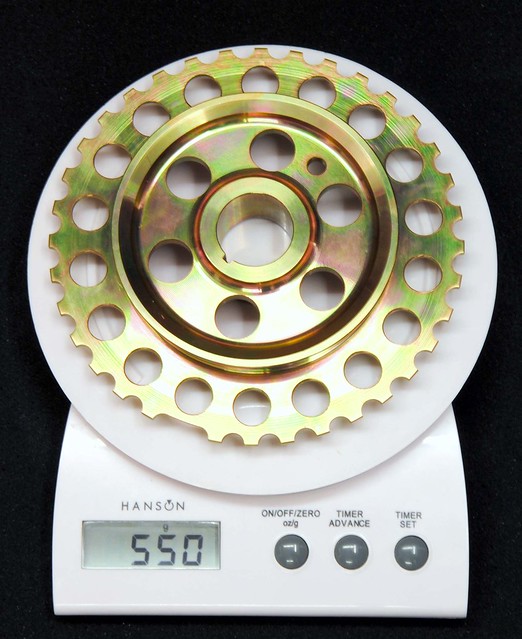
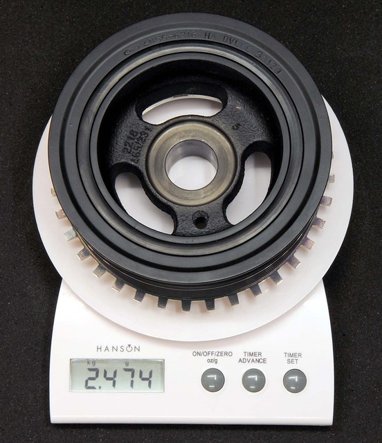
To go with the keyed crank is the Sb Developments small pulley. The standard pulley is 2 KG heavier. Apart from the obvious advantages of reduced mass, I'm curious about the impact this will have on the inherent vibration of an 'in-line' 4 cylinder engine. No doubt the heavier pulley helps to smooth things out, but does it add to, or reduce, the stresses in the crank?
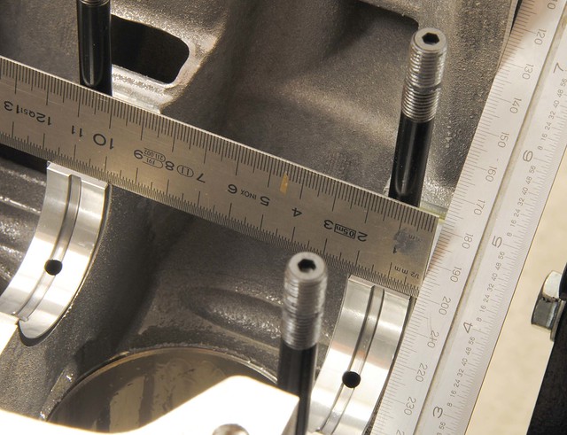
It was always my intention to 'blue print' the engine so a bit of time was spent positioning the main shells on the webs. The Ford assembly guide gives measurements to center the shells to the oil holes in the crank. The block casting is not perfect, so you can't rely on centering the shell on the web to get this right.
A little care here will maximise oil flow to the big ends.
The ladder is treated the same way, but, as it is also machined and honed in-situ, the final tweak is to align it with the block before torquing down.
I am using the the original graded Ford bearings and there's little I can do to change clearances. But better the devil you know, so I checked them with Plastigauge. Much to my relief all the bearings produced identical measurements and all nicely square. The clearances were bigger than the Ford declared spec of 0.039 mm - probably due to me only using half the specified torque for the check. I am happy, however, that the full 60 ft-lbs on the ARP studs squeezed this up tighter, and it felt 'nice'. I've used Millers Assembly Lubricant this time (I normally use engine oil). Starting it for the first time may be interesting as it is really thick sticky stuff!
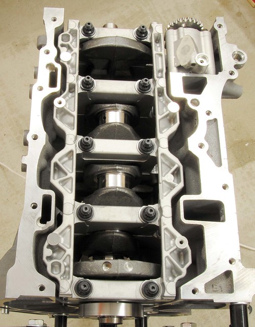
And finally all all back in place and torqued up
To go with the keyed crank is the Sb Developments small pulley. The standard pulley is 2 KG heavier. Apart from the obvious advantages of reduced mass, I'm curious about the impact this will have on the inherent vibration of an 'in-line' 4 cylinder engine. No doubt the heavier pulley helps to smooth things out, but does it add to, or reduce, the stresses in the crank?
It was always my intention to 'blue print' the engine so a bit of time was spent positioning the main shells on the webs. The Ford assembly guide gives measurements to center the shells to the oil holes in the crank. The block casting is not perfect, so you can't rely on centering the shell on the web to get this right.
A little care here will maximise oil flow to the big ends.
The ladder is treated the same way, but, as it is also machined and honed in-situ, the final tweak is to align it with the block before torquing down.
I am using the the original graded Ford bearings and there's little I can do to change clearances. But better the devil you know, so I checked them with Plastigauge. Much to my relief all the bearings produced identical measurements and all nicely square. The clearances were bigger than the Ford declared spec of 0.039 mm - probably due to me only using half the specified torque for the check. I am happy, however, that the full 60 ft-lbs on the ARP studs squeezed this up tighter, and it felt 'nice'. I've used Millers Assembly Lubricant this time (I normally use engine oil). Starting it for the first time may be interesting as it is really thick sticky stuff!
And finally all all back in place and torqued up

Re: Duratec in detail
Nice  I assume your flywheel is going to be lighter than the normal one also? It doesn't look like the original ford pulley had any rubbery stuff in it, so I am not convinced the standard part will do much to counter shaft vibration anyway ...
Cheers,
Robin
Cheers,
Robin
I is in your loomz nibblin ur wirez
#bemoretut
#bemoretut
Re: Duratec in detail
Yes, the flywheel is as light as i can go with the standard starter - also going for a smaller diameter multi-plate clutch which is lighter too. Watch this space

Re: Duratec in detail
Thanks for the update. I am really enjoying the thread - your photos and explanations are excellent - you could write a book! 
-
KingK_series
- Posts: 567
- Joined: Tue Jan 05, 2010 10:10 am
Re: Duratec in detail
David wrote:
The water pump is a conventional set-up. The cone shape impeller fits in a cone shape that has been machined in the block - coolant being sucked into the centre and thrown out to a ring in the housing - not unlike a turbo charger in appearance. The coolant exiting from the pump is split in two - one flow being directed to each side of the block for even cooling. On a high RPM engine it will cavitate, so steps need to be taken to slow it down and this can be done with either with a larger pulley on the pump or a smaller one on the crank.
its not just the pump speed that will cause cavitation - this open backed design, the gap between the pump and bearing mount and the gap between the blades and block casting are all notorious for causing cavitation - its bad cheap design, just as similar pumps on the K Series and Honda K20A2/Z1,2 are, and just as teams who race Hondas fit their K20s with a better design, I consider it half the battle to stop so called "HGF' on the K.
-
KingK_series
- Posts: 567
- Joined: Tue Jan 05, 2010 10:10 am
Re: Duratec in detail
David wrote: To go with the keyed crank is the Sb Developments small pulley. The standard pulley is 2 KG heavier. Apart from the obvious advantages of reduced mass, I'm curious about the impact this will have on the inherent vibration of an 'in-line' 4 cylinder engine. No doubt the heavier pulley helps to smooth things out, but does it add to, or reduce, the stresses in the crank?
Your OEM pulley does have a rubber damper in this photo - second ring in from center, and it is designed to damp out torsional vibration and reduce the amplitude of resonant peaks.
removing it, especially if pistons/rods/crank/flywheel remain substancially OE or OEM weight will increase fatigue in the crank and shorten its life - However the K series damper is designed to facilitate a OEM crank life of a minimum of 400,000 miles! - so in practice they can be disposed of but only if the crank is carefully crack tested at every build, its life will be shortened without the damper -
-
KingK_series
- Posts: 567
- Joined: Tue Jan 05, 2010 10:10 am
Re: Duratec in detail
Blueprinting the block has nothing to do with oiling, it always means remachining every machined surface in an OEM block to a much higher tolerance than OEM, this is done to reduce friction and increase engine life.David wrote:
It was always my intention to 'blue print' the engine so a bit of time was spent positioning the main shells on the webs. The Ford assembly guide gives measurements to center the shells to the oil holes in the crank. The block casting is not perfect, so you can't rely on centering the shell on the web to get this right.
- it is a very difficult thing to get right,,,,,, I have wasted thousands and scrapped many blocks getting it to a standard that qualifies for the name 'blueprinted' - the chief difficulty is finding machinists competent enough to do it, - it also cost a fortune in jigging that is required for any individual engine.
despite the difficulties it is however the most rewarding thing to achieve and anyone driving a properly bluepriinted engine, however experienced will notice the difference immediately.
-
KingK_series
- Posts: 567
- Joined: Tue Jan 05, 2010 10:10 am
Re: Duratec in detail
David wrote: The ladder is treated the same way, but, as it is also machined and honed in-situ, the final tweak is to align it with the block before torquing down.
I am using the the original graded Ford bearings and there's little I can do to change clearances. But better the devil you know, so I checked them with Plastigauge. Much to my relief all the bearings produced identical measurements and all nicely square. The clearances were bigger than the Ford declared spec of 0.039 mm - probably due to me only using half the specified torque for the check. I am happy, however, that the full 60 ft-lbs on the ARP studs squeezed this up tighter, and it felt 'nice'. I've used Millers Assembly Lubricant this time (I normally use engine oil). Starting it for the first time may be interesting as it is really thick sticky stuff!
if those caps are not dowled before align honing, they will never be square with all the care in the world - worse they will move all over the place when the engine revs = wear and friction.
Re: Duratec in detail
Wow! a lot of comments there!
The only thing to pick up on is the alignment of the main caps (ladder). Mazda/Ford don't use dowels (on this engine anyway) and the ladder is an interference fit with the block, i.e. as you pull it down, the caps engage a slot machined in the block for them. This is a tight fit and requires some force to both fit and remove, so there's little chance of any lateral movement unless the whole block flexes. Longitudinal movement, on the other hand, is not located and my adjustment was to locate it to where it had originally been machined. The Duratec does have a reputation of being very strong around the bearings.
As far as 'Blueprinting' is concerned, I think you being a bit picky. It is a generic term that's been around for longer than the internal combustion engine itself. It's definition, as a verb, is 'to follow a detailed plan'. Aligning the shells to the measurements specified in their drawing is exactly that. Generally, I'm just making sure the engine will be built within the tolerances set out in the factory assembly document (drawings).
-
KingK_series
- Posts: 567
- Joined: Tue Jan 05, 2010 10:10 am
Re: Duratec in detail
David wrote:Wow! a lot of comments there!
The only thing to pick up on is the alignment of the main caps (ladder). Mazda/Ford don't use dowels (on this engine anyway) and the ladder is an interference fit with the block, i.e. as you pull it down, the caps engage a slot machined in the block for them. This is a tight fit and requires some force to both fit and remove, so there's little chance of any lateral movement unless the whole block flexes. Longitudinal movement, on the other hand, is not located and my adjustment was to locate it to where it had originally been machined. The Duratec does have a reputation of being very strong around the bearings.
As far as 'Blueprinting' is concerned, I think you being a bit picky. It is a generic term that's been around for longer than the internal combustion engine itself. It's definition, as a verb, is 'to follow a detailed plan'. Aligning the shells to the measurements specified in their drawing is exactly that. Generally, I'm just making sure the engine will be built within the tolerances set out in the factory assembly document (drawings).
I'm sure you are right in terms of your use of the word blueprint in generic terms - I use it specifically in terms of engine building, and measures/ processes universally accepted to improve engine life and reduce friction losses.
In terms of bearing caps - you might want to look at any American book on blueprinting big American V8s, Engines such as these as used in Indy and famously Nascar use the same design as the Duratec and the builders go to enormous lengths to dowel the caps - it is essential in a 'blueprinted' engine and especially one with old fashioned bearing caps - it is one of the reasons I prefer the K since K has the much more modern crank carrier design - in fact K was the first production engine to bring it from F1 - a bearing carrier design where the whole lower crankcase is one massive stiff structure. The Americans have some ingenious and well practiced procedures around this type of design which are very sound - and I have drawn on in other areas of the K's block - take a look at the books.
- Of course crank carrier type engines can be improved by doweling too - the K uses just 2 locating dowels - all my engines are machined for 10 dowels and then the surfaces faced, so the crank path can be align honed - bloody difficult and very expensive, I've cussed and swore a year of my life away to get it and the right people to get it right, but the result is massive. Even in a road engine - in fact it is the one thing I like about the K20 - the Honda people copied the K design, but then dowled all 10 webs. almost perfect, because in the production Honda the bearing path is as with all production engines align bored rather than honed, and there will always be 'jump' between journals - so the path is never straight, but at least on the Honda its not dancing about like something off Strictly !
Re: Duratec in detail
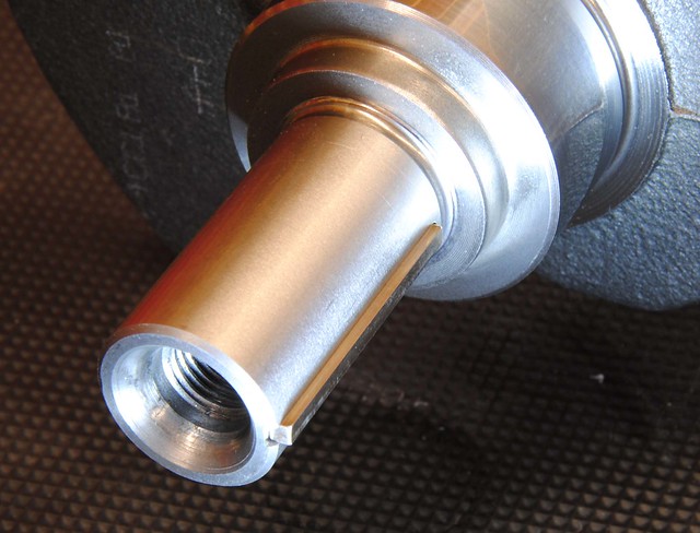
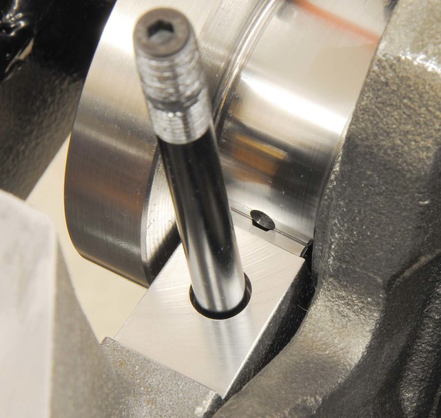
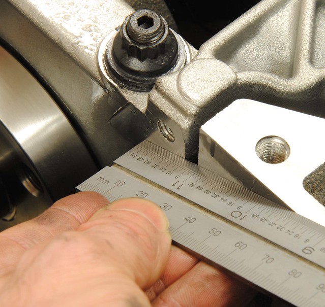
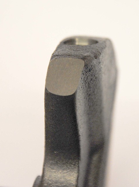
The Duratec crank has a flat ground on one of the counter weights. This is to calibrate it for use with the TDC peg which screws into the block.
I made one up while with a 10 mm bolt - carefully grinding it to the correct length. It does make life easier for setting things up and is worth the effort.
Time to move on to the pistons assembly. First thing was to gap the rings - all were bang smack in the middle of the Cosworth tolerance for 250 BHP engine, so it didn't take long.

The second ring has a groove at it's bottom edge - the exact function of this groove is up for debate, but it's likely to help with reducing oil passing upwards and provide a downward pumping action. The flow of oil past piston rings is an interesting subject - but too involved to cover here.

The oil expander ring has a ridge too - this time it is clearly for the retaining rings to hold it in place.

I am Using 12.5 CR Supertech pistons and Carrillo (Cosworth) rods. Ford specify a weight tolerance between their standard pistons that amounts to approximately 3 grams. The Supertech pistons were within 2 grams of each other and the Carrillo rods were within a gram. The gudgeon pins were identical in weight. By grading and matching the components I manage to get each piston assembly to within a gram of each other. The new piston and rods are 66 grams lighter than the standard items.


All four pistons assembled, which was straightforward, except for maybe the cir-clips which are always tricky if you haven't got the right tool. But my confidence took a knock when I was left with two circlips. Self-doubt took over and I had to remove all the pistons to check! But all were present and correct - very funny Supertech
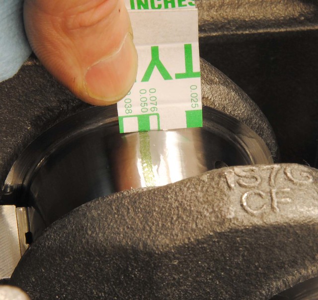
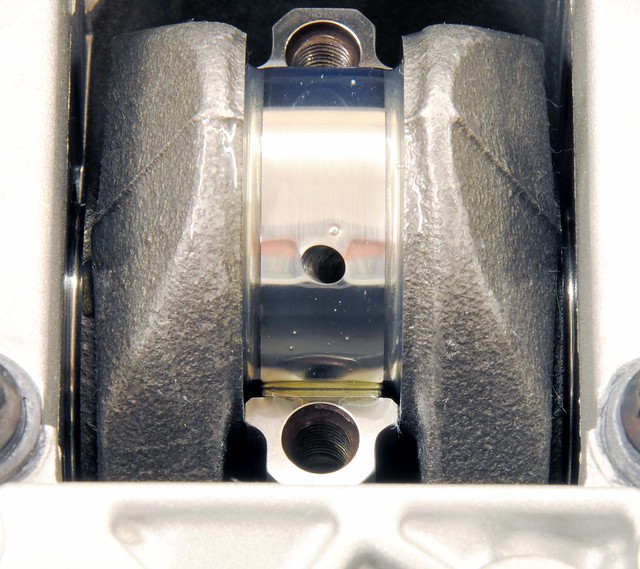
The bearing shells are uprated VP from Cosworth.
I used plasti gauge to check them - all being near the 0.038 mm band which is again in the middle of the Cosworth (and Ford) spec. Not quite as even as the mains, but all well within tolerance.
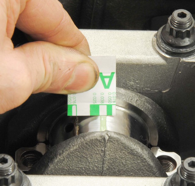
It is worth noting that the bearings look narrower than the cap, in fact, I think it is 2.5 mm. This coupled with a groove in the crank journal provides a reservoir of oil in the bearing and helps to protect the bearing at times of low pressure by allowing oil to recirculate as the hydrodynamic pressure goes negative on the unloaded side.
I did get Simon, at Ultimate Performance, to assemble the head after the CNC work (mainly to stop the hassle or ordering cam followers) but I do intend to 'reassemble' it my self. But with the pistons in, it meant I could check the valve-to-piston clearance.
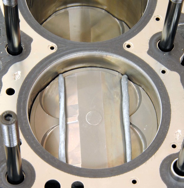
So with some blue tack on no.1 piston, the head was put on with an old gasket, cams timed, and then the crank rotated.
There was no hard contact (relief!) and so the head was removed to see how close things got.
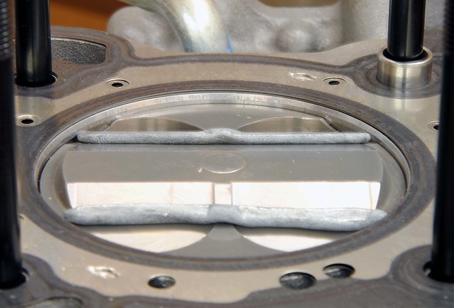
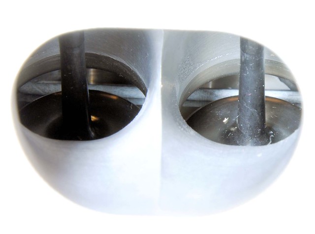
Nothing was too close and amazingly you could see it all happen through the inlet port!
With clearance check done, time was spent dismantling the head and putting it back together. It is not that I don't trust Ultimate Performance to do it right, it was just that I wanted to go through the full process of the engine build myself. But full marks to Simon at Ultimate Performance - every valve was perfect


I was glad to spot this nasty bit of shaving firmly embedded in the cam bearing. It was very hard so probably debris from the valve seat machining - maybe during manufacture at Ford. I levered it out to leave just an indentation which I'm sure will do no harm.

I made one up while with a 10 mm bolt - carefully grinding it to the correct length. It does make life easier for setting things up and is worth the effort.
Time to move on to the pistons assembly. First thing was to gap the rings - all were bang smack in the middle of the Cosworth tolerance for 250 BHP engine, so it didn't take long.
The second ring has a groove at it's bottom edge - the exact function of this groove is up for debate, but it's likely to help with reducing oil passing upwards and provide a downward pumping action. The flow of oil past piston rings is an interesting subject - but too involved to cover here.
The oil expander ring has a ridge too - this time it is clearly for the retaining rings to hold it in place.
I am Using 12.5 CR Supertech pistons and Carrillo (Cosworth) rods. Ford specify a weight tolerance between their standard pistons that amounts to approximately 3 grams. The Supertech pistons were within 2 grams of each other and the Carrillo rods were within a gram. The gudgeon pins were identical in weight. By grading and matching the components I manage to get each piston assembly to within a gram of each other. The new piston and rods are 66 grams lighter than the standard items.
All four pistons assembled, which was straightforward, except for maybe the cir-clips which are always tricky if you haven't got the right tool. But my confidence took a knock when I was left with two circlips. Self-doubt took over and I had to remove all the pistons to check! But all were present and correct - very funny Supertech
The bearing shells are uprated VP from Cosworth.
I used plasti gauge to check them - all being near the 0.038 mm band which is again in the middle of the Cosworth (and Ford) spec. Not quite as even as the mains, but all well within tolerance.
It is worth noting that the bearings look narrower than the cap, in fact, I think it is 2.5 mm. This coupled with a groove in the crank journal provides a reservoir of oil in the bearing and helps to protect the bearing at times of low pressure by allowing oil to recirculate as the hydrodynamic pressure goes negative on the unloaded side.
I did get Simon, at Ultimate Performance, to assemble the head after the CNC work (mainly to stop the hassle or ordering cam followers) but I do intend to 'reassemble' it my self. But with the pistons in, it meant I could check the valve-to-piston clearance.
So with some blue tack on no.1 piston, the head was put on with an old gasket, cams timed, and then the crank rotated.
There was no hard contact (relief!) and so the head was removed to see how close things got.
Nothing was too close and amazingly you could see it all happen through the inlet port!
With clearance check done, time was spent dismantling the head and putting it back together. It is not that I don't trust Ultimate Performance to do it right, it was just that I wanted to go through the full process of the engine build myself. But full marks to Simon at Ultimate Performance - every valve was perfect
I was glad to spot this nasty bit of shaving firmly embedded in the cam bearing. It was very hard so probably debris from the valve seat machining - maybe during manufacture at Ford. I levered it out to leave just an indentation which I'm sure will do no harm.
Re: Duratec in detail
Almost makes me want to build an engine ... but actually I prefer drinking tea and watching somebody else do it on the internet Good stuff ... like the plasticine sausages for valve clearance test!
I is in your loomz nibblin ur wirez
#bemoretut
#bemoretut
-
KingK_series
- Posts: 567
- Joined: Tue Jan 05, 2010 10:10 am
Re: Duratec in detail
robin wrote:Almost makes me want to build an engine ... but actually I prefer drinking tea and watching somebody else do it on the internet
Absolutely!
good sound careful engine building -
- if only some of the K ""engine builders" did the same...... see thread on what I don't like what gets done to the K,,,, and pics of pistons with valve pockets hacked out by hand only to still hit the valves.
this sort of practice is very nice to see and should be an everyday standard.