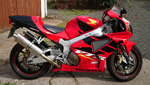
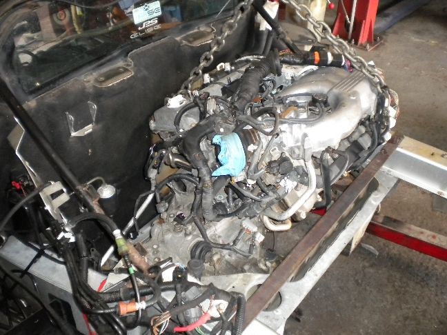
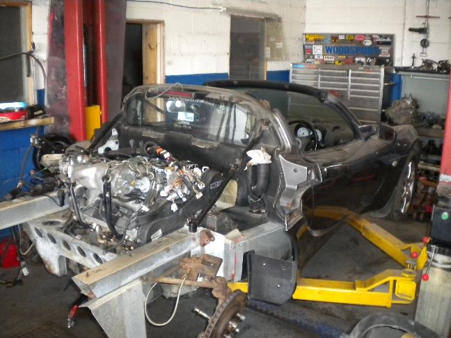
For years now i have wanted to carry out one of our awesome V6 transplants on an Elise, but we have always been so busy with Mr2 stuff that it never happened, but i thought it was time to get one under our belt to prove this can be done and very successfully. I put the word out a few months ago that i was after a "test mule" to carry out our first Elise conversion and was approached by one of your members (don't know his forum name here yet!) but his names Kevin and this is his car on our lift ready for surgery....
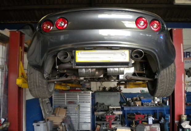
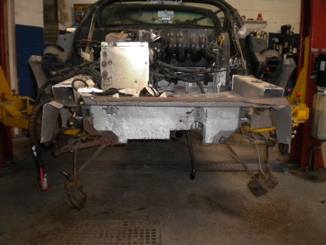
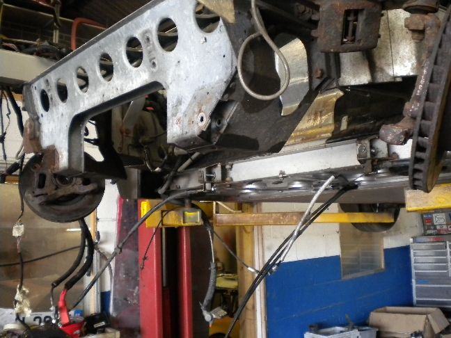
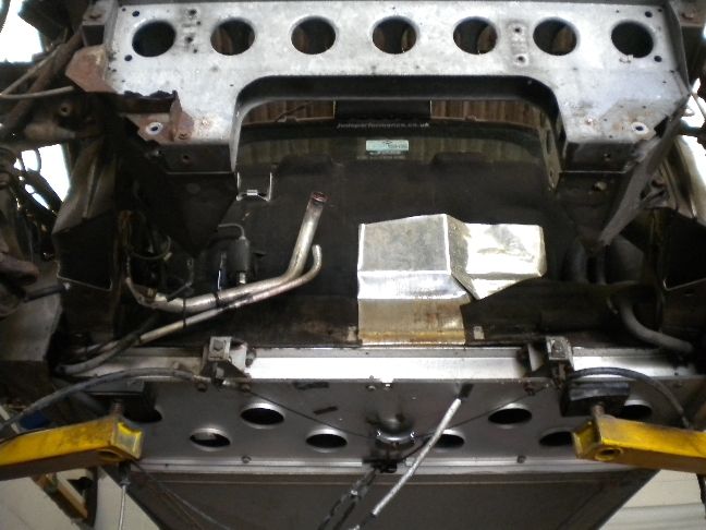
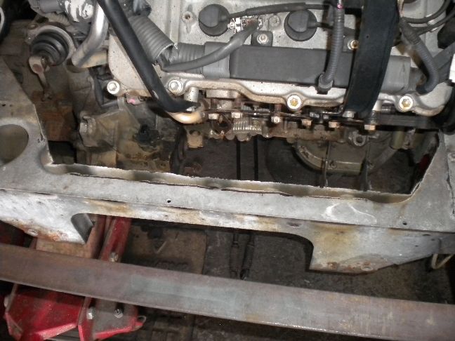
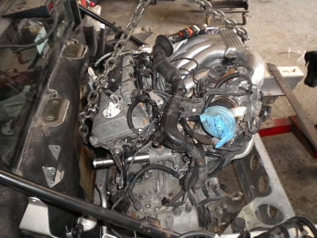
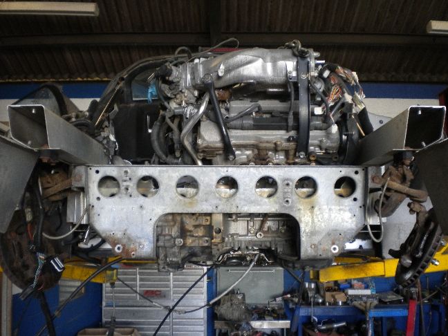
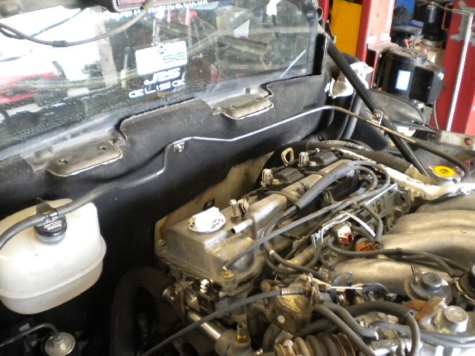
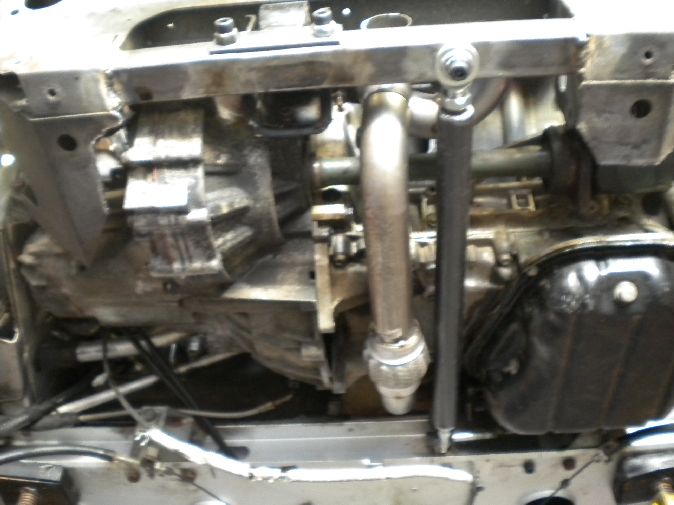
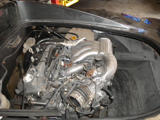
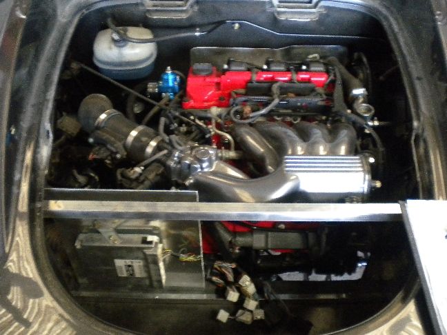
I have removed the rear undertray to inspect the task ahead, there is not a lot of room in that bay but we are well used to squeezing big engines into small spaces...
The remainder of this project can be read here at the end of this thread http://www.scottishelises.com/phpbb/vie ... &start=300
I will be removing the rear clam next, dropping the subframe off and removing the engine/gearbox.
So this is officially his build thread on the project, i will be documenting every part of it here as it happens, hopefully get to know a few of you along the way!
Update 12/5/11
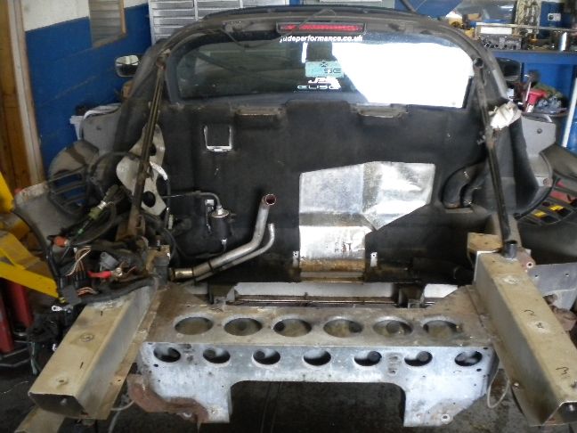
Officially day 1 of the build, we started by removing the seats, the rear cabin plastic trim and the clamshell to expose the heart of the beast....
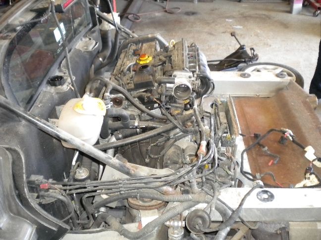
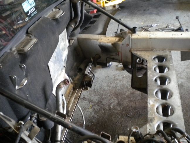
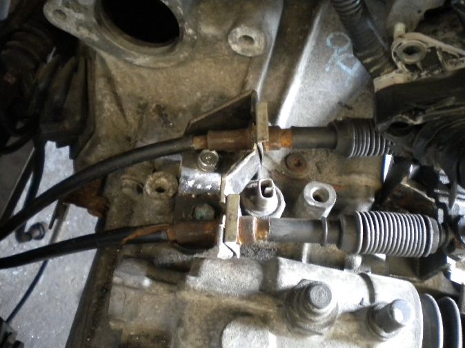
The usual amount of snapping studs and rusty bolts you'd expect really, all of which will be restudded and restored during the rebuild.
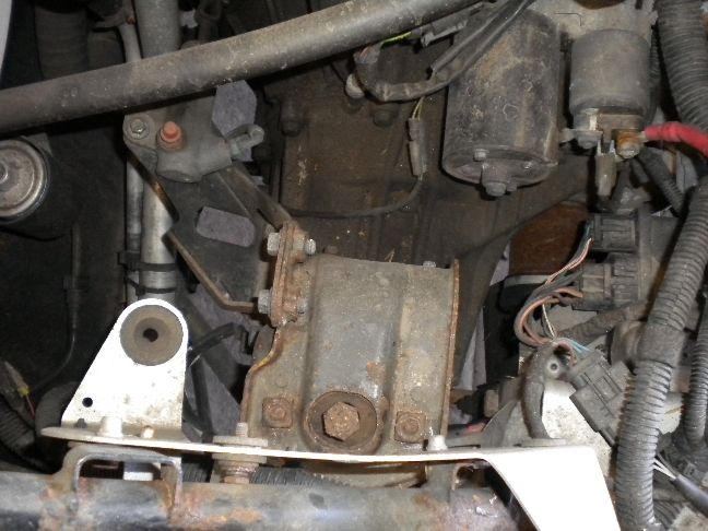
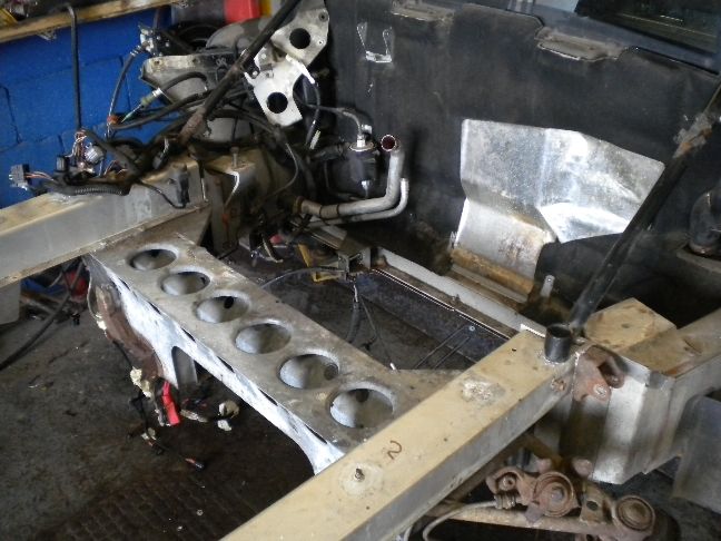
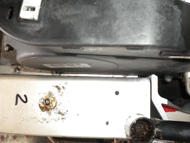
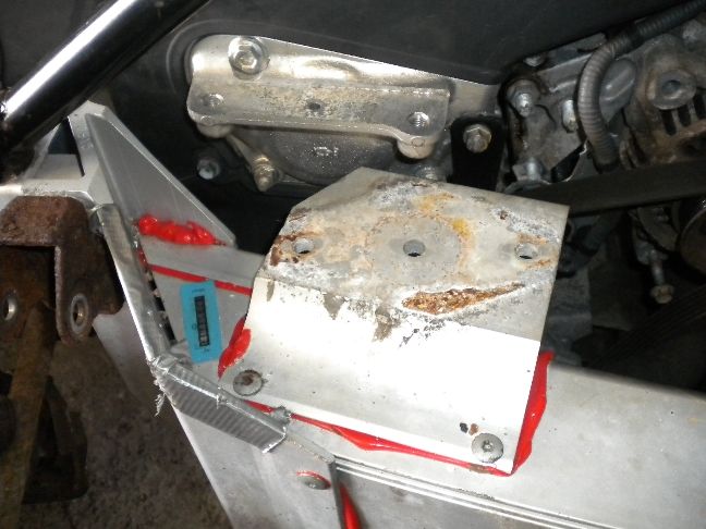
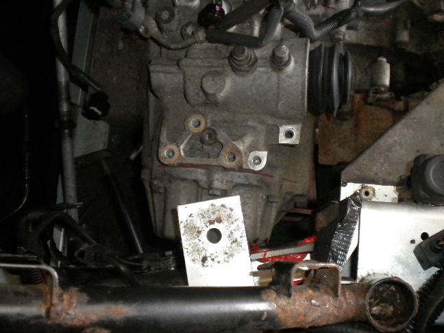
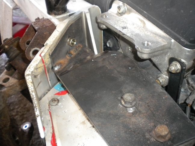
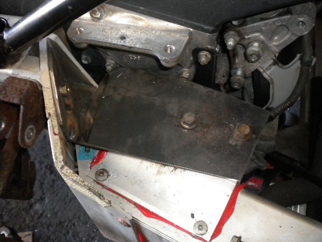
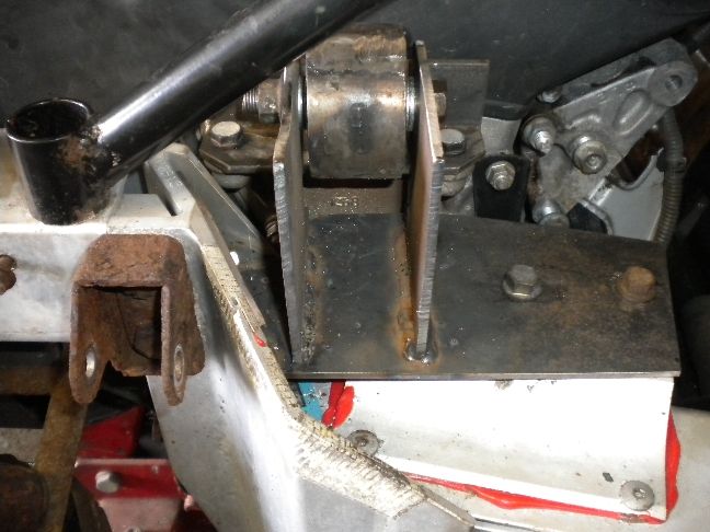
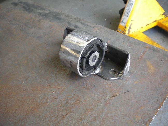
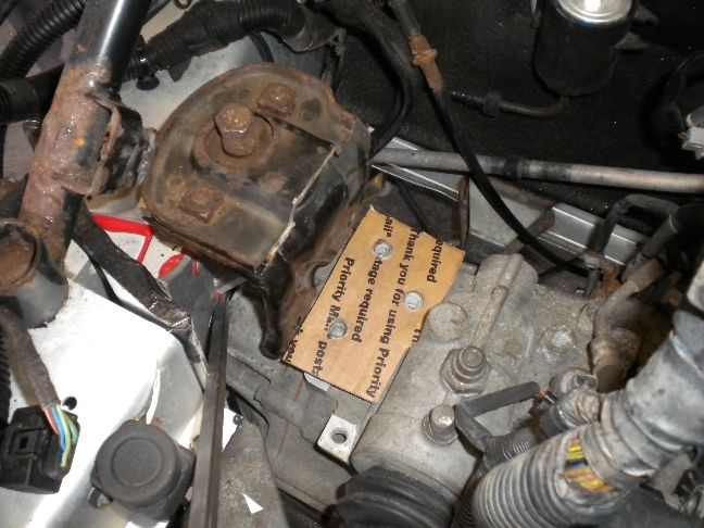
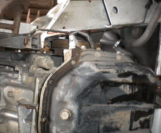
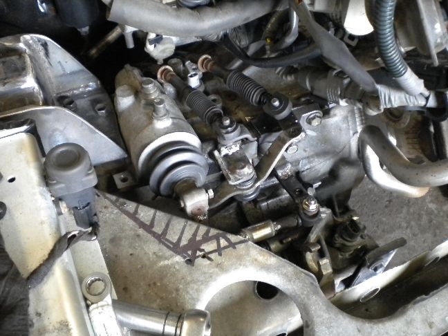
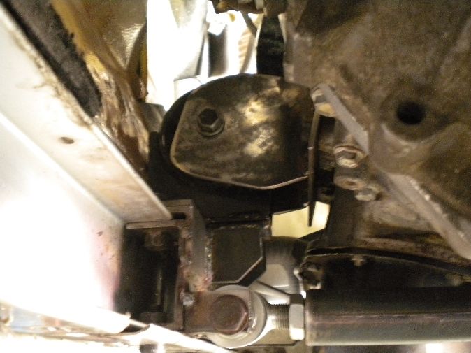
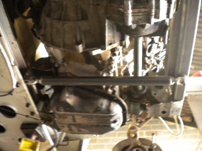
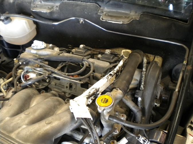
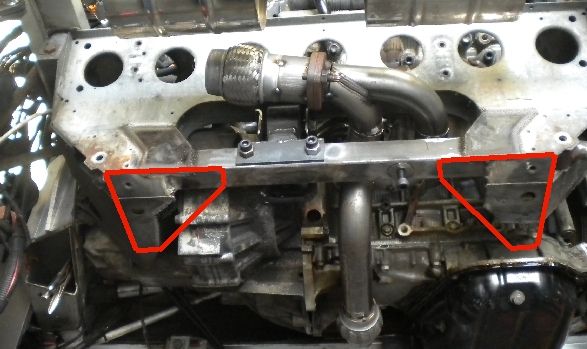
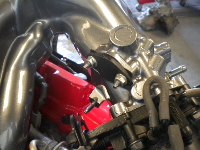
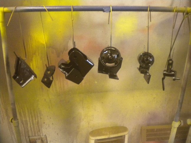
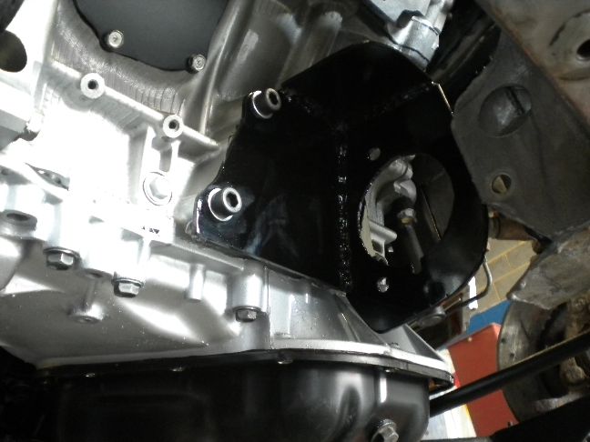
Some reference shots of the current engine mounts...
The day ended with removal of the driveshafts and exhaust system...
With this new access (i wish we had the same access to our Mr2 engine bays!) i was able to throw the tape measure across a few key areas, it's going to be tight but i can't see any major problems at this stage.
UPDATE 13/5/11
Engine and gearbox now removed, pretty simple compared to our Mr2 stuff to be honest, the only thing i'm not impressed by is the K series build quality, plastic crap all over it, everything looks liable to snap or fail at any time! It just doesn't have the solid build of a Toyota engine at all.
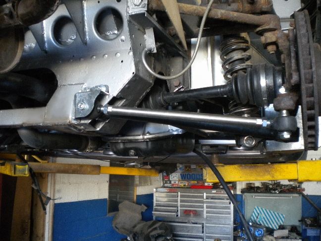
Wishbones and tie rods removed, not because i needed to, but because they are a bit manky so i felt they could do with a refurb.
Engine mount shots for reference....
I didn't get a chance to clean the bay down today, that's a job for next week.
UPDATE 17/5/11
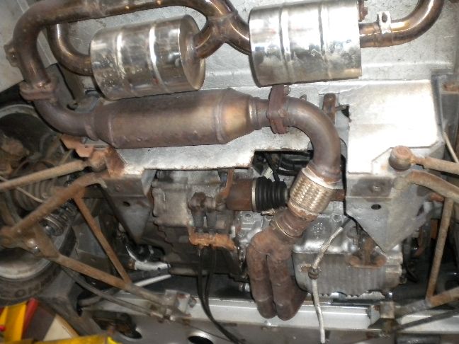
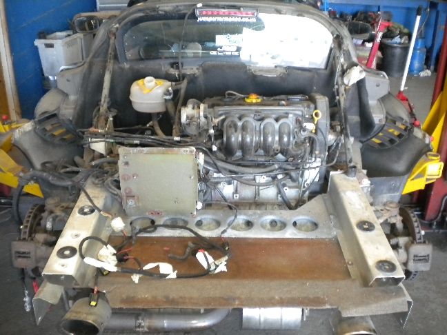
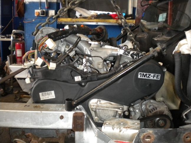
I got the 1mz mated to a Celica gearbox (my preferred box of choice on this build for gear selection reasons) and test fitted it into the bay, it became immediately apparent that the project was not going to go any further without modifying the rear subframe, there just wasn't the room for the rear exhaust manifold to recess into, so i took the decision to remove part of the subframe. We are no strangers to this sort of thing and beefing this back up to be just as strong as it was before is very easy, and if i found something that prevented the project happening at all then i could always rebuild this to be as good as it was before, if not stronger.... but for now part of it had to go.
With that removed i was able to get the engine into an acceptable position, there are still some modifications to do in certain areas but it just about fits right now.
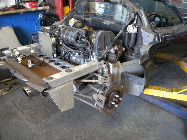
Tight in places but clearing....
Sump height is excellent, about level with the floor...
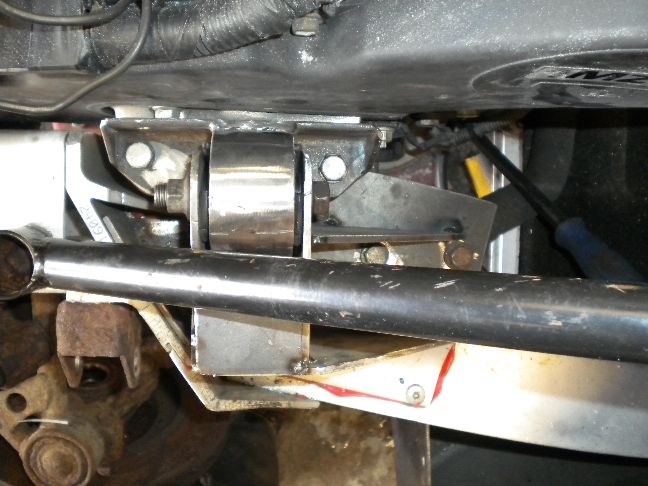
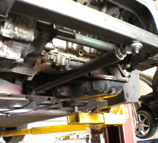
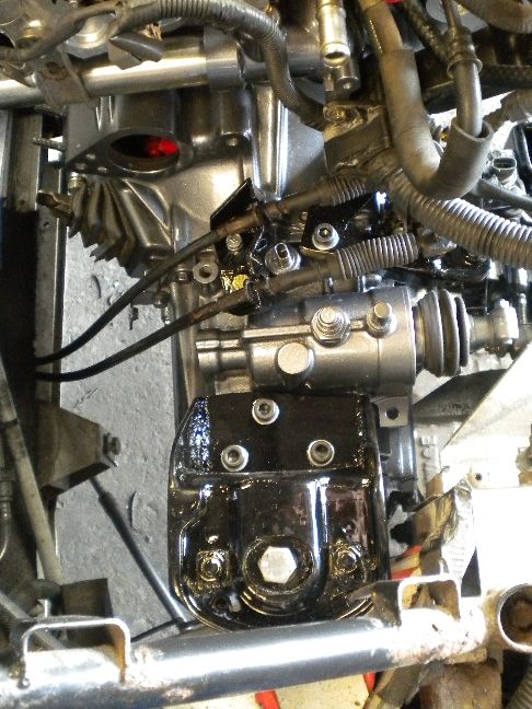
Engine and gearbox mount reference shots...
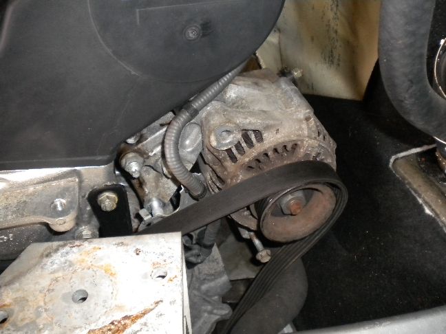
Alternator dummy fitted, it will need new adjusting assmebly making but it clears...
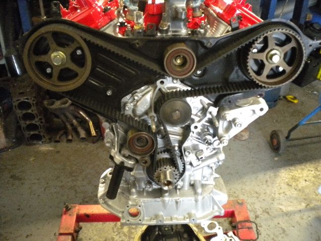
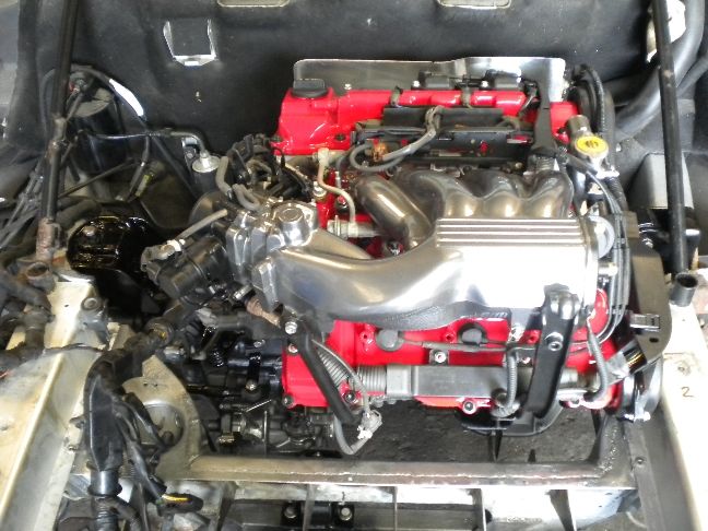
Overview.... please bear in mind this is the raw fabrication stage, there is no flyhwheel or clutch fitted and everything will need to come apart again after fabrication is finished for the engine rebuild and detailing work to begin....
UPDATE 18/5/11
Today i got the engine hung in exactly the right place, perfect alignment in all planes and had to do a little trimming and adjusting of a few key areas to get a happy engine position, but it is now sat exactly where it needs to be, i have had issues clearing the drivers side front wishbone mount but this has now been sorted.
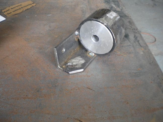
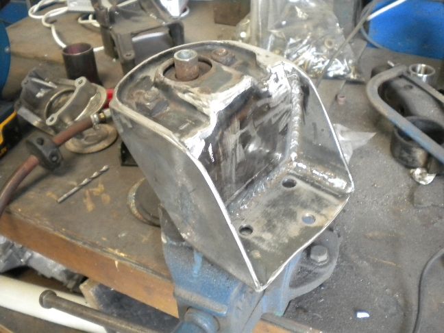
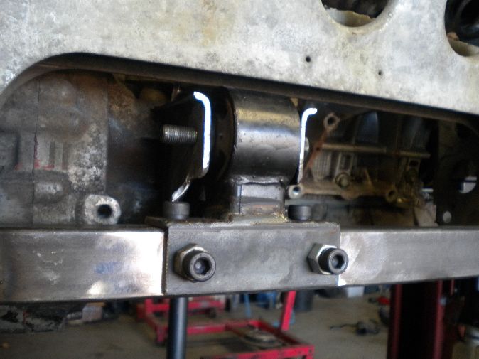
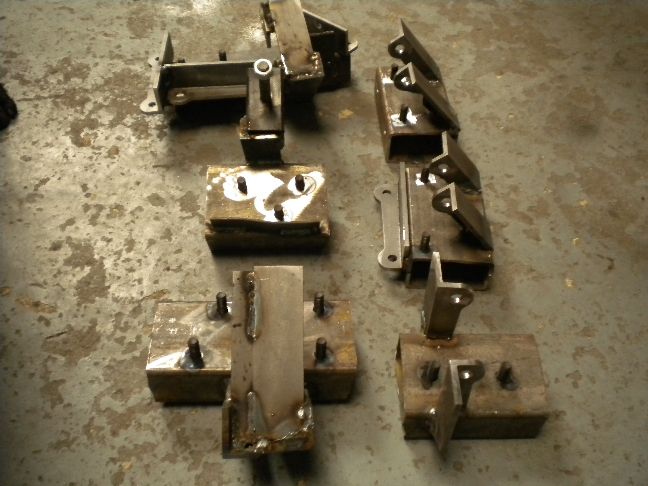
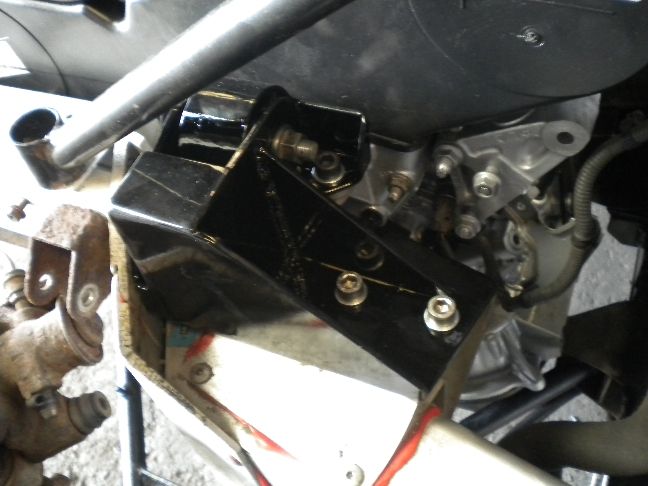
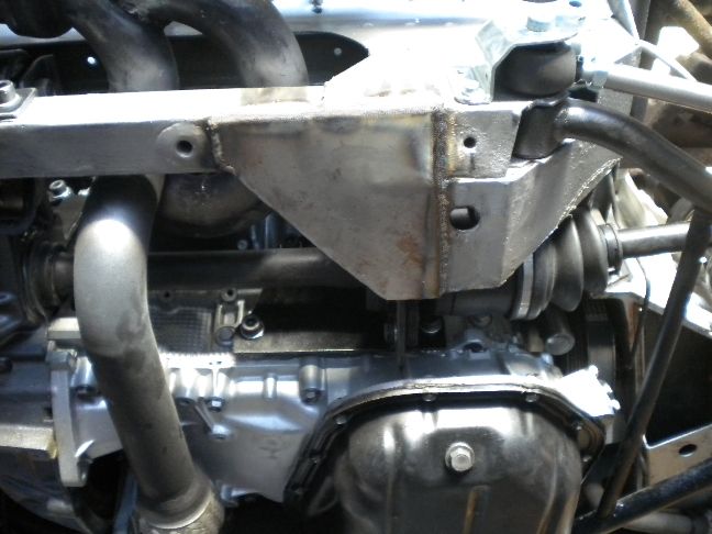
With the engine position finalized i have begun fabrication of the right side mount, starting with this base platform, i have made a support tab on the rear to add another bolting point. From this platform i will make the uprights and bracing to carry the new engine mount. As before this is just fabrication stage, so everything will come apart for final dressing and painting.
This mount needs another 5 or 6 pieces to make it complete, the left side mount is going to be very much simpler to achieve.
UPDATE 19/5/11
Today saw a lot of progress on the mounts, on the drivers side i made the engine side hanger, this starts off as a basic angle section with a thick wall tube welded to it and we inserted our alloy dummy bush into this (centres the bracket and allows welding to take place without damaging a rubber version)...
This is then bolted to the engine and washers added either side to copy the dimensions of the actual rubber bush we will be using, then we added brackets to the chassis plate to hold this bush...
Next the brackets need supporting, this is done with a back plate that ties both brackets together and onto the chassis plate, all just tacked for now, the seam welding will take place when this is removed for final dressing etc....
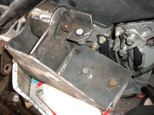
Another brace added at the front of the bracket...
Then both brackets are tied together with a top hat...
This has given us a very strong, dare i say it over-engineered mount that doesn't weigh much.
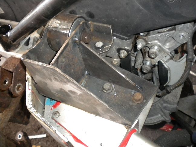
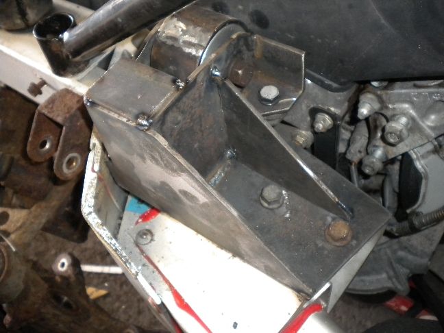
Next the engine bracket is removed and we added end gussets to the angle as well as inserting the actual rubber bush...
This is the "finished" drivers side mount assembly...
All that remains here is to seam weld it, dress it up, radius the corners, prime it and paint, but for now it is done.
I started work on the passenger side mount which is a much easier affair, i decided that part of the original K bracket could be used here, so i removed one half of it and made a template for the gearbox end...
This bracket is a bit rusty, so i will be using our electrolysis bath to restore that.
I then made some "sides" for the mount which restore all of its previous strength plus some, very strong and a pretty simple solution. I still need to add a drop plate onto the vertical face of this mount, seam it all up and dress it etc.... you get the idea...
So with both hanger mounts complete the engine was free hanging for the very first time...
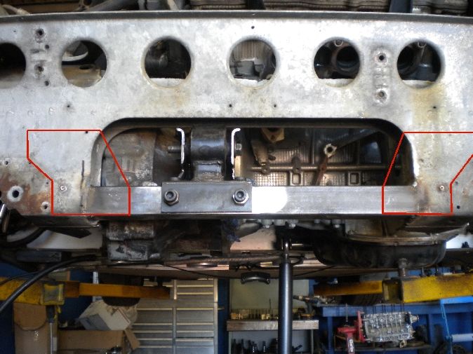
As you can tell by our mounts alone we don't do things without serious consideration to strength, the rear subframe will get similar treatment, all coming in due course.
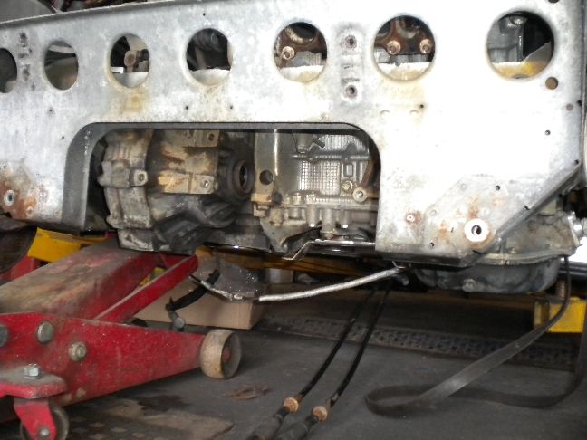
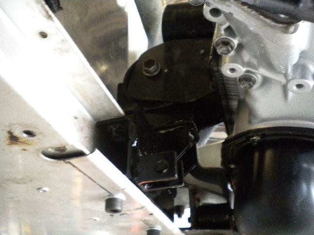
From underneath you can see how tight my tolerances are on this swap...
I'm looking forward to tearing the engine down for the final assembly and detailing stage, that's when things really start looking pretty.
UPDATE 20/5/11
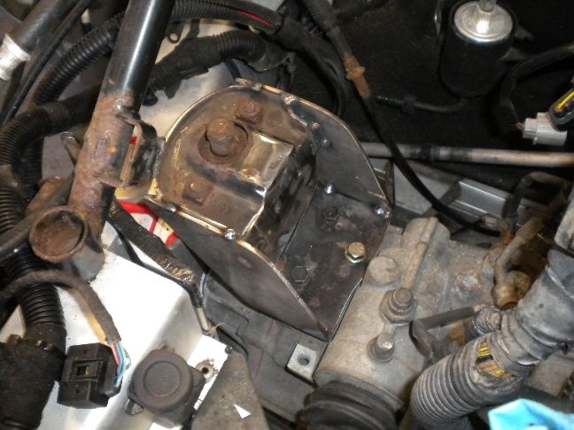
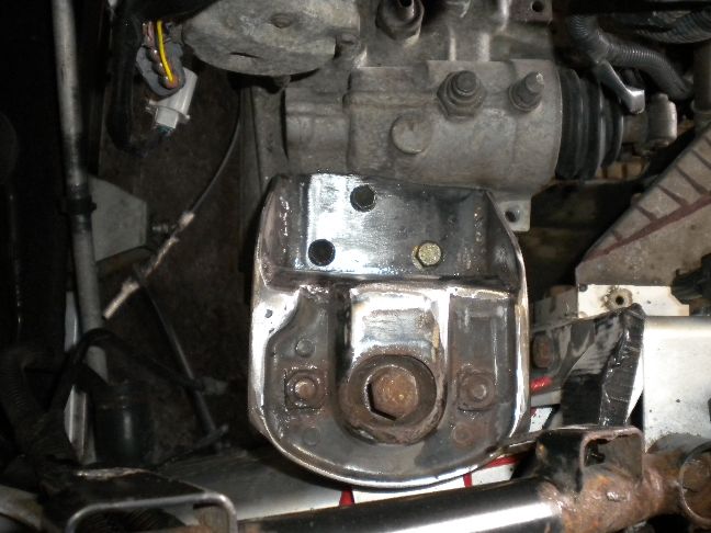
Today i finished the passenger side gearbox mount, it no longer looks like the original welded to separate plates, but in fact a mount that could have been produced by the factory, so that for me is mission accomplished.
The mount in situ...
An overview of the project so far....
UPDATE 27/5/11
Over the past few days i have been working on the gearshift solution, and it hasn't been easy at all but i have found a way to make it all work.
I have managed to retain the K cables and by re-routing them over the gearbox and making a whole new selector assembly it is a workable solution. The problem i came across was that the Elise has very little "throw" on its gear selector cable, the "gate" cable was fine, it had enough throw (travel on the cable if you like) to operate the linkage from 1st/2nd across to reverse.
However the linkage setup that i use for the Mr2 Mk3 v6 conversions was not going to work here, a Mk3 Mr2 throws a lot more (almost double) on the selector cable than the Elise, so i had to extend one of the linakge arms and shorten another to gear down the throw at the linkage.
What this means in real terms is that a small movement of the stick now results in a larger movement at the gearbox end.
Here is my rough prototype linkage set up, nothing is finished or dressed, just tacked together to prove it works. What you are looking at is a modified Mk3 Mr2 linkage bolted to brackets that attach to the Celica gearbox, and it's these Mk3 Mr2 linkage arms that have been adjusted to make it all work. It takes days of fine tuning to get this right and only a few hours to make it all look pretty which i will do on final assembly, but for now it works.
I still have the cable locating bracketry to make, but that's simple in the scheme of things.
UPDATE 31/5/11
The gear selection is now mechanically finished, i made a holding bracket for the cables, it was a complicated little bugger, about 6 different plates went into it to clear everything but i'm pleased to report the gears all change very slickly and this is a huge part of the swap out of the way.
These parts have all been removed now for final dressing and painting.
UPDATE 1/6/11
As with any first time build a lot of the modifications need to be tested to see if they are going to work or not, all we can do is apply the best idea we can to the issue at hand, engineer a way around it and see how it performs. If it is a problem later on then we find another way, such is the nature of a first time conversion. The conversions that we have done hundreds of are so tried and tested now that there is nothing left to debug.
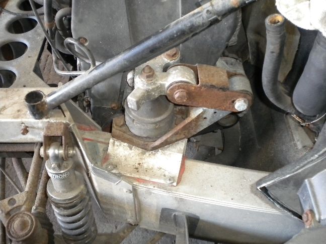
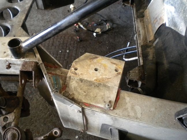
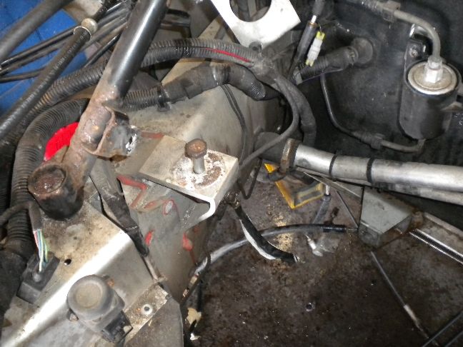
One such area that we have built a prototype solution for is a front torque mount, now i was a little reluctant to have one on this car, i am trying to minimize cabin vibration to a bare minimum, but until we try this we simply won't know if it's going to work or not. We have several other ideas on how to go about an alternative, but if this works it should give a very stable engine.
We have built an insert, much like the wishbone mounting points, except ours effectively "clamps" the chassis rail as well as being bolted to it, i have also internally braced it.
From this insert section i have attached the torque mount and made a bracket coming off the block, this is the raw welded stage of all brackets....
You can see a rosejoint coming off the lower part of the chassis insert, that is part of the second stage of reinforcing the rear subframe, i haven't shown you stage 1 yet but seeing as i was doing the front torque mount it made more sense to do this part now.
I have tied the rear subframe together with 40mm box and made this fully adjustable tie bar that runs from the front mount to the rear subframe. The rosejoints are opposite handed so i can adjust the preload on the bar to help brace everything.... good idea or not? Again i won't know until we try it out, but we are applying all of our knowledge and experience to the various problems at hand.
I have two more of these braces planned to tie the subframe into the car better than it currently is, which could be used on a stock engined car come to think of it, more on that when i make them.
I have some pretty good subframe reinforcing coming as well, and none of this is costing us too much weight.
UPDATE 2/6/11
Today saw the rear torque mount fabrication completed, i used the original K rear torque mount because it was the only one that would fit in the space i had, i can insert a stiffer rubber into it if need be to fine tune it though, we shall see.
The subframe brace has four captive nuts inside it for the torque mount. Again nothing is pretty right now, this is still the raw fab stage. Also ignore the spacer nuts being used on the rear of the torque mount, i shall be using correctly sized cap head bolts there instead.
Now i have heard from some of you that cracking on the subframe has been an issue in the past on other conversions, due to the differences in the thickness of steel welded in and the welds being the weakest point. So i am planning on speading the load from that member with plates that are in between the subframe and box section thickness, also acting as gussets...
That is just one of the planned upgrades for the subframe, i have quite a few more coming.
UPDATE 6/6/11
Work continued today, we are still in the raw fabrication stage, this build has taken perhaps more time to fabricate everything than any other conversion i think i have ever done, but the finished build quality should reflect that.
Today i decided to do a few of the smaller finishing off jobs that we usually leave until the last few days of the build, but i wanted to get all of the making stuff out of the way. I have converted the Elise coolant bottle to an "Mr2 type" expansion bottle, i don't like the way the Elise deals with the coolant at all, in fact it could be contributing to the demise of the K having it vent off excess pressure to atmosphere with no reservoir to draw fresh stuff back in. I know of a few cars that do it this way but i think it's crap, so the Mr2 system will be employed which uses a "tidal" ebb and flow past the pressure cap on engine cooldowns, linked to an expansion bottle, so whatever coolant the engine needs, it gets, without fear of it running (or boiling) dry.
So the Elise bottle is no longer a pressurized bottle, it just handles the overflow. I also made an expansion pipe for this bottle, now on most builds you will see a piece of rubber pipe routed from point A to B, that is not how things are done at Woodsport nor Toyotas way of doing it, a factory looking hardpipe is made with rubber only at each end is much more the done thing....
It needs painting and final finishing but it's stuff like that that looks like it's always been there, we thrive on that way of working.
The NS rad pipe has been sorted, using the original Elise pipe cut to fit and part of the Elise hardpipe, i'm going to make a bracket for that pipe to secure it to the chassis, again the way Toyota do stuff.
The OS rad pipe was a simple Mr2 pipe joined straight onto the original Elise one, no pic because it's boring, who wants to see two bits of rubber joined together!
The clutch hydraulic line was a tricky little bugger, it has a double flare on its end and inside the Mr2 slave cylinder housing is a single flare, so although the Elise end screwed straight into the Mr2 slave (gotta love inter-manufacturer compatability!) it would not seal due to the coned ends not having the same flare, so i made this adapter.
The throttle cable was also sorted, pretty much a bread n butter thing to do, attach a cable to a bracket and hook it into the throttle quadrant.... simples!
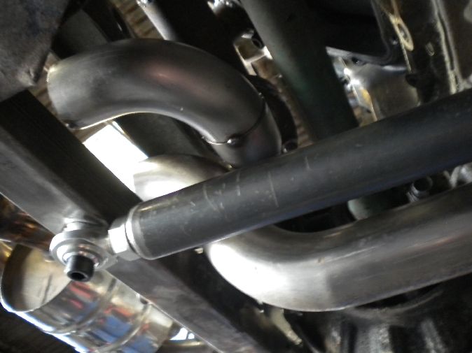
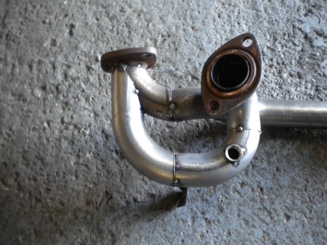
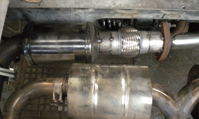
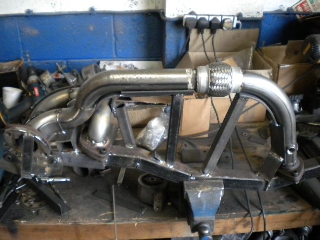
I decided to finish the day by starting work on the exhaust system, this is the front bank pipe leading under the sump, i have a short flexi on it.
From there it sweeps up and over the subframe reinforcer, navigating both supported shaft and the front bank pipe which just does two 90* turns to exit through the subframe hole...
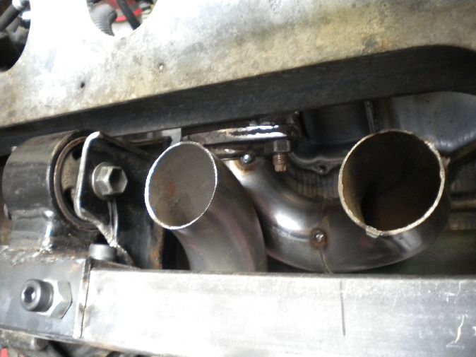
So this is what i am left with.... two pipes, one from each bank coming over the subframe bar, now it gets tricky, these have to merge together, have flanges on them so that the system can be removed and also lead into a CAT/DECAT section before entering the silencer, not simple at all with such little space to play with.
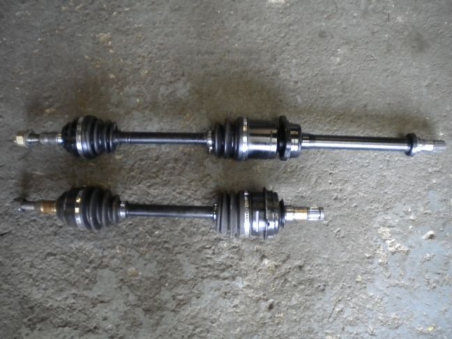
Ok so you know i am detailing every part of this conversion but there is one bit that i am afraid i'm keeping to myself, and that is exactly what i am doing about the driveshafts. I will say they are Toyota based, and i am having a very nice supported shaft set up that gives an equal length halfshaft arrangement (something that's missing from the Elise K setup).
My reasons for witholding that part of the conversion is that i have put more research into that bit than any other part of the build and i have been all too often copied in the past by some plageristic twat who decides to offer the very same conversion using my build thread as a blueprint for "their" swap, so it's a little bit of protection on my part. Likewise the wiring will not be detailed either, it will just be "today i wired the whole thing up" wiring done, i hope you chaps understand my reasons for not detailing certain aspects, it's not funny watching all of your R&D work pop up on another garages menu.
UPDATE 7/6/11
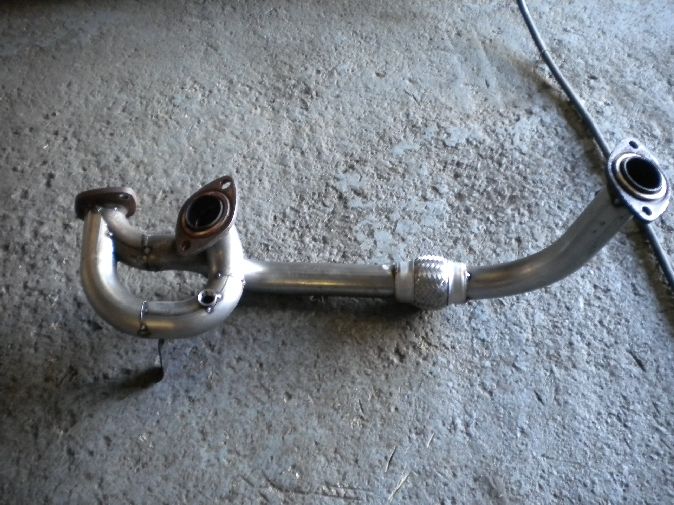
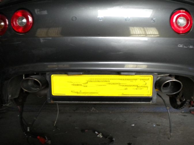
Today saw more exhaust work, i managed to couple both banks together and into one flange. The main importance being that the whole front section needs to be removable both for seam welding it up and for future maintenance, far too many things get modified these days without thought as to how to actually remove it or access stuff. I also got the subframe gussets added that i thought about a few days ago, these are hopefully helping to spread the load from the reinforcing member i added so the total loads aren't just on my welds. I have also added the centre section flexi, this will be coupled to a sports CAT when it arrives and into the Elise back box. I'm pretty happy with the current exhaust design.
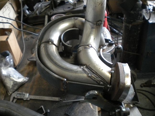
The front pipes removed and lambda bosses added...
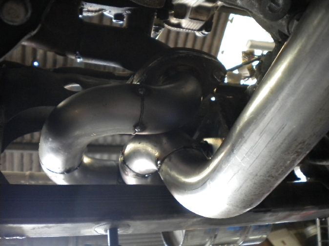
A close up view of the system making its way through the maze
So all in all it's mission accomplished on the exhaust front, just seam welding and final dressing on that needed during the rebuild.
EDIT: While uploading the pics i spotted another area i can beef the subframe, i think two nice plates in these areas could add a bit to both my subframe member and the subframe itself...
UPDATE 8/6/11
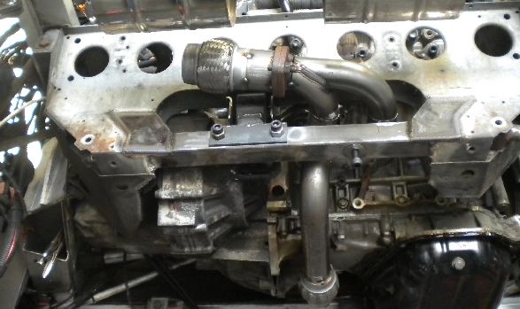
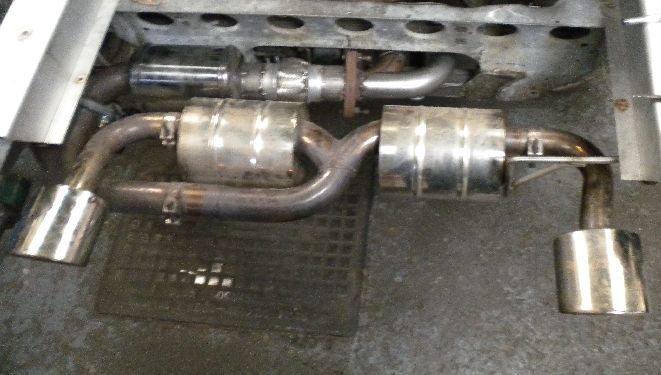
Today saw completion of the fabrication stage of the build, i have finished the exhaust fab (still to seam weld), but it is complete with a sports CAT and all flanges.
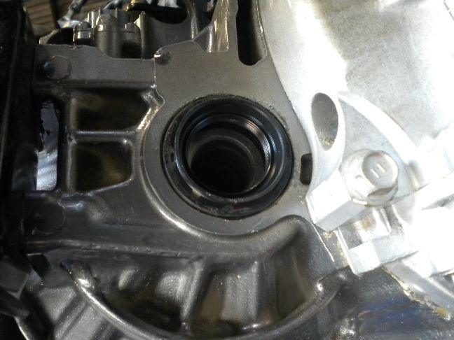
The last thing to fabricate before tearing this whole thing back down was the rear driveshaft bearing carrier. On the Mr2 projects we like to include a supported driveshaft set up, it's much prefered than using one long and one short shaft, you get less torque steer on the rear end and it's just a far nicer way of doing things. For the supported shaft to work it needs a simple 3 piece bracket, we have been making these for years so they are a well tried and tested part.
Here it is in its basic welded stage... we basically plasma cut out all of the plates, and weld them together in a jig i have that places the bearing carrier in the correct spot, get this wrong and the gearbox output seal will leak oil.
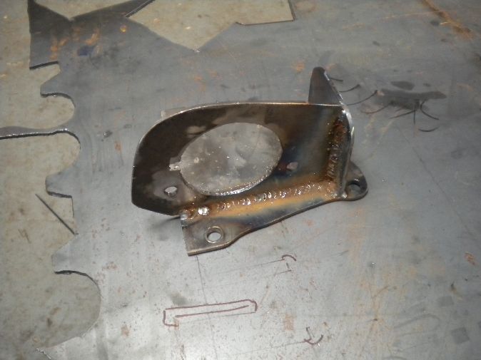
As with every part i have had to make over the last 3-4 weeks they will all need dressing, priming and painting before final assembly.
Next job is to pull the engine back out, strip everything down and rebuild.
UPDATE 10/6/11
Just before the engine comes back out i decided to take advantage of everything being in place and refitted the rear clam. We knew we would have to make alterations to the boot wall divider so that was removed to see how things looked. All in all pretty good, there will still be a useable boot and the wall i put back in will be unboltable around the rear bank of spark plugs for access.
I have added a full length sealing rubber that now goes the whole way around both engine bay and boot.
I am going to fabricate the new boot wall on Monday before the engine comes back out. The exhaust is also now hanging perfectly, it was all over the place on the K series...
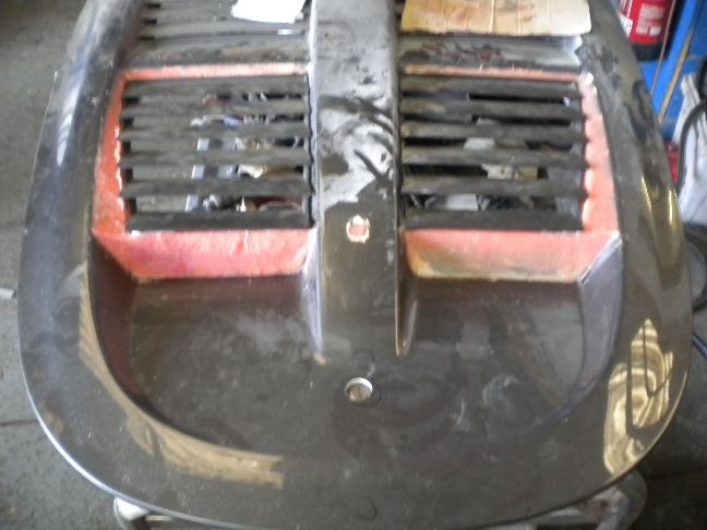
We also knew that the engine lid would need modifying, the vented areas just extend too far into the engine bay to clear the rear plenum chamber, so after some careful thought about how to approach this we have decided to remove the original vents, build up the areas around them and reseat the vents, basically it should look like a stock lid (or very closely themed) but with the necessary clearance underneath for the engine.
The start of modifying the lid involves making two rear sections, these are aluminium and serve as the basic structure for our fibral. At Woodsport we do a lot of body modifications and painting work so this is relatively simple and the end result should look stunning.
I plan to relocate the lid lock and catch mechanism to the new boot wall so it retains all of its original functionality.
The clam and engine lid have not needed as much modifying as i thought they would which is a huge bonus.
UPDATE 13/6/11
Ok time to kick this project into second gear, with all fabrication finished the engine and gearbox were removed from the car along with all of my newly fabricated parts which will now go for final finishing and detailing.
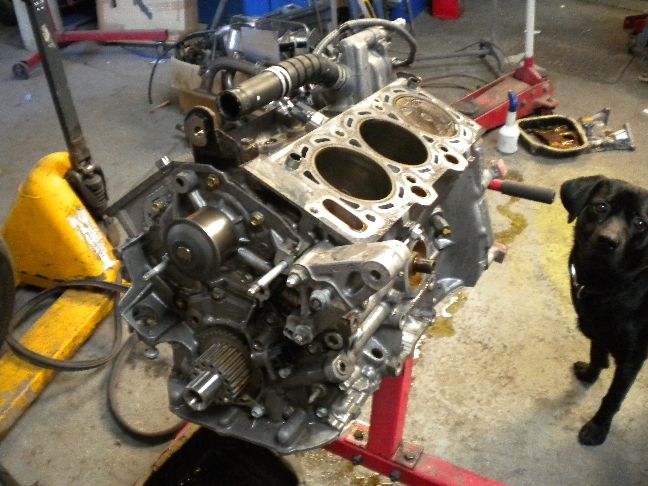
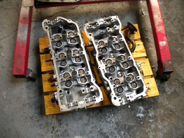
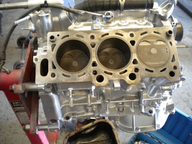
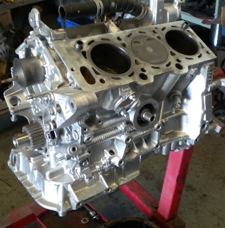
I stripped the V6 down to the block, inspecting as i went, and the engine is in superb condition (all of these Camry V6 engines always are, way over engineered)
I haven't cleaned the block face or pistons yet but the rest of the block has been thoroughly cleaned and inspected (Alfie looks on approving the build, in case you haven't seen him on the webcams or previous pics, Aflie is Woodsport dog)
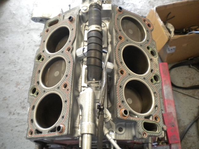
This is what quad cams and 24 buckets looks like...
Everything is to be checked against manufacturers spec and if found to be outside of tolerance replaced, but we never see any wear on these units, this one still has its factory bore honing marks on the cylinder walls, in fact they normally do even on engines with 150k+... these engines are a different class. Woodsport has carried out over 150 V6 swaps over the years and i've seen maybe 2 engines in that time with any significant wear.
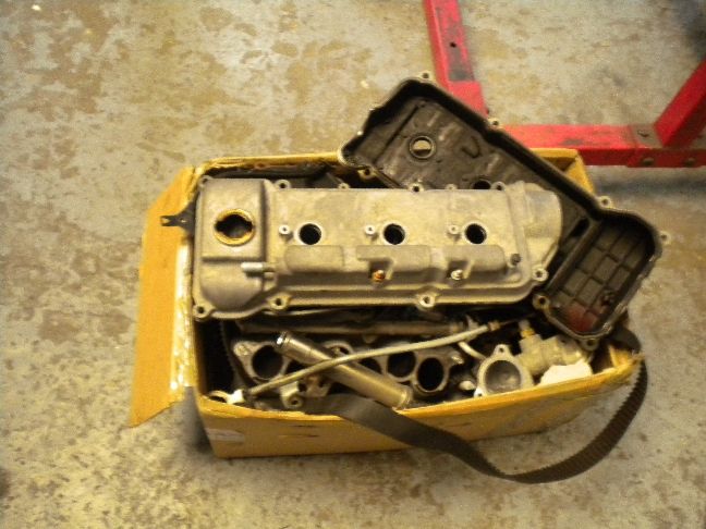
A big box of engine parts all destined for restoration...
The heads have come up like new...
So there's another full days work easily still in the block and probably a full week in restoring engine parts/painting etc
Every conversion we do gets a new water pump, timing belt, thermostat, oil filter and any other consumable item we can replace, along with only the best quality gasket sets we can buy (usually Payen), no cheap chinese parts on our builds.
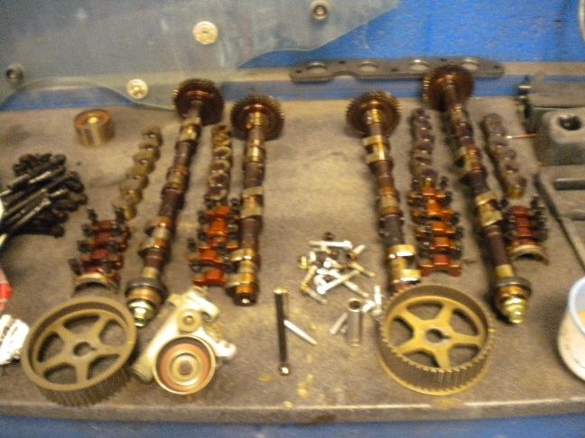
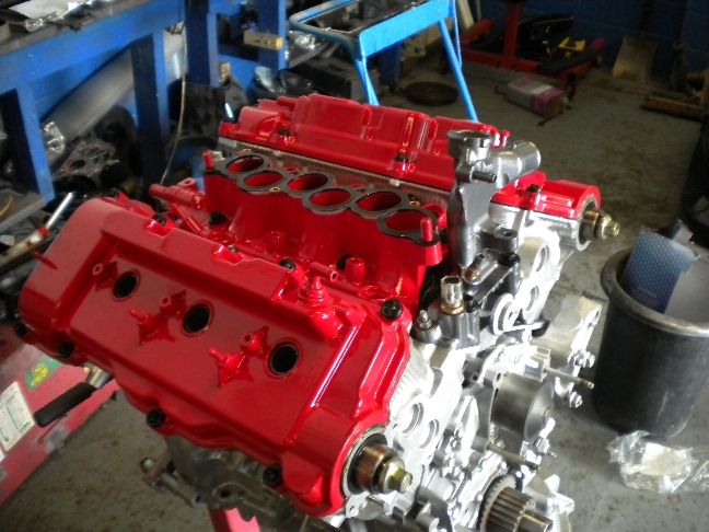
UPDATE 14/6/11
Today saw the block cleaning complete, all bearings have been checked and found to be good. The block has been treated to acid cleaning and silver paint, this will get a clearcoat layer to make it "pop" . Very little of this gets seen in the engine bay but the devil's in the detail so they say. The lower sump casing has been resealed and refitted with brand new bolts, no need for new bolts, the old ones would have done perfectly well, but we have thousands of new Jap bolts to choose from so why not. Every single bolt that can be replaced will be if for no other reason than cosmetics.
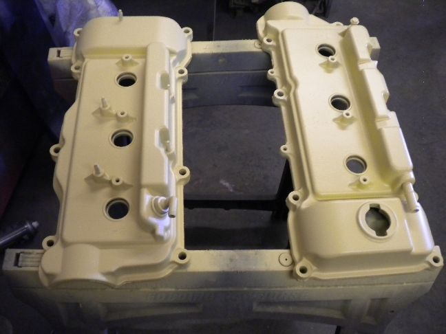
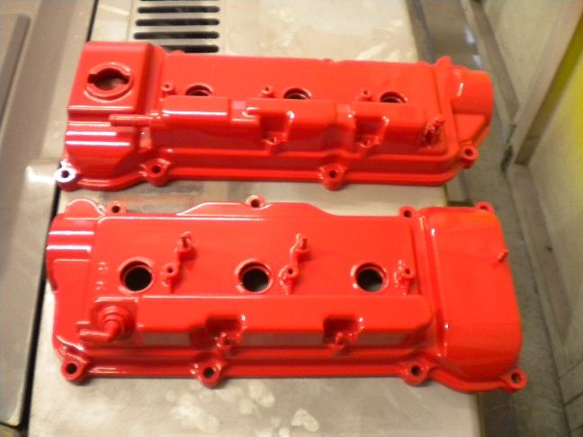
Six hours was spent on the cam covers and plenum chamber, first they were pressure washed off with degreasing solvent, then treated to an acid wash to remove any alloy corrosion, followed by a cellulose wash to remove any carbon on the inside and a final pressure wash to leave them immaculately clean.
They were then flappy disc'd down to remove any factory casting marks and ridges (makes the engine parts so much more pleasing to the eye) and finally panel wiped down with er.... panel wipe :p
Lastly a thick high build etch primer is applied to all parts to be painted, this high build takes out the last of the imperfections left from the flappy disc. Tomorrow this primer layer will be 500 grade sanded to leave the parts with a marble smooth finish on which to apply the basecoat colour and topcoats. All of this effort will make the engine parts bang like a whores headboard
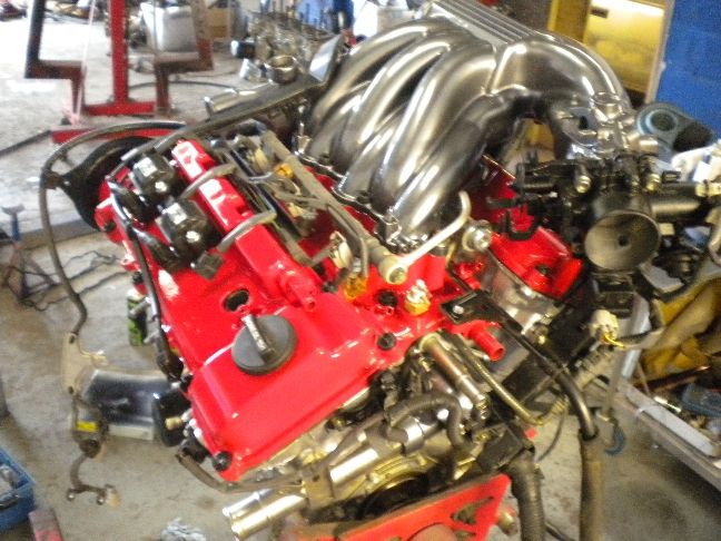
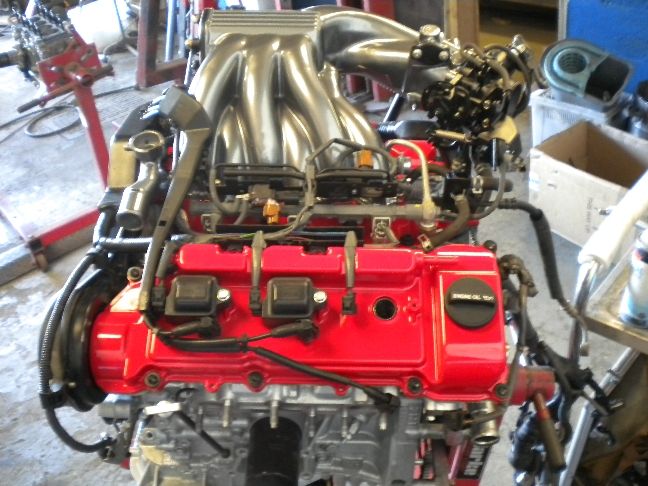
The colour scheme chosen for this engine is gunmetal grey and red, to match the cars exterior and interior, should look pretty good.
Building the engine up with every small detail taken care of is what i really enjoy, the fabrication part is ok i supoose, but it's this stage i love the most and our show standard engine bays are world famous now. Not only does it have to work 100% but it must look the part, anybody can sling an engine in.
UPDATE 15/6/11
HUGE pic update today, we got a lot of work done today so this is very pic heavy.
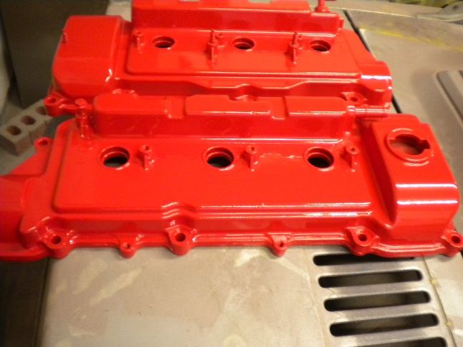
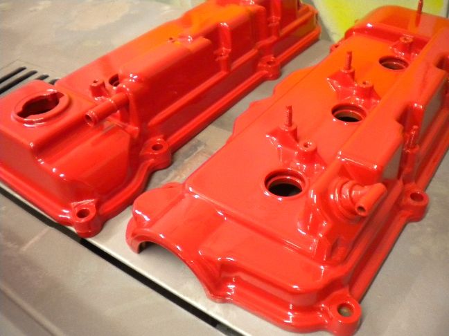
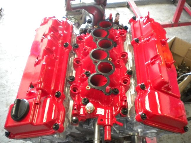
The cam covers were painted and have turned out as expected, like strawberry coloured glass as someone put it, this is the benefit of all that prep work...
These will keep their shine for years even with the heat from the engine.
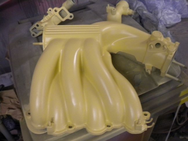
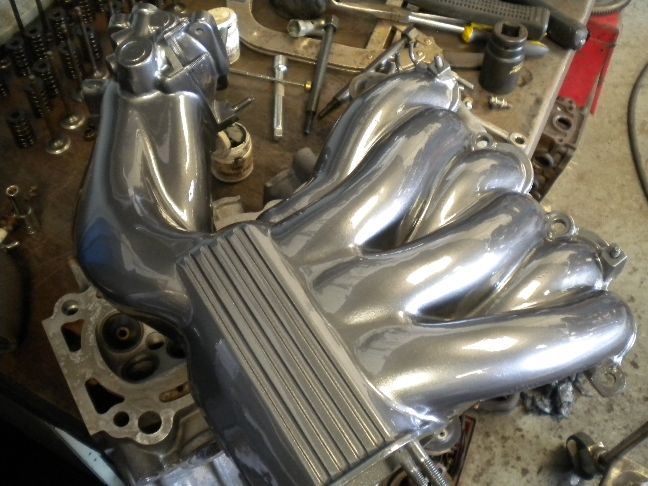
The plenum also got finished, we mixed this shade of gunmetal ourselves to make it pretty unique, looks like the terminators ribcage
We only have one standard of finish here, perfection.
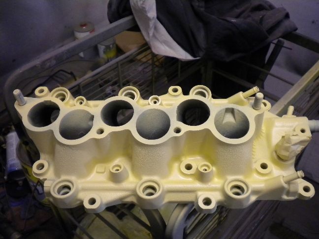
So with those drying (hotter than hell here today so drying times are very quick) i got on rebuilding the heads, on with the new gaskets...
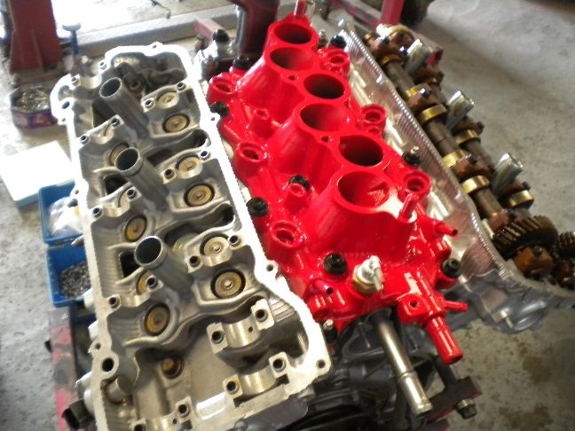
Heads torqued down, there's a 3 stage proceedure on these, also fitted the newly painted centre lower plenum with all new bolts and gaskets...
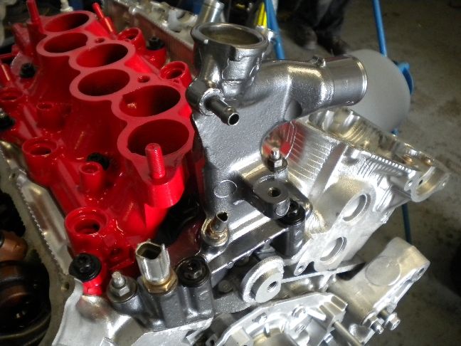
Coolant filler point painted and all sensors restored, check out the new brass bases...
With the cam covers touch dry they could be refitted...
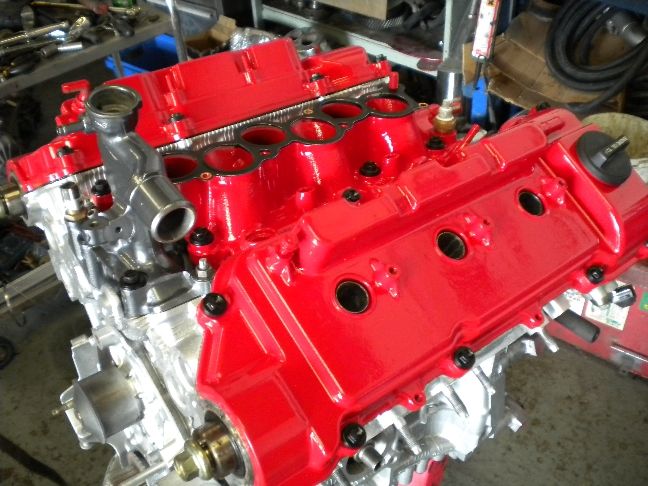
Fuel injectors and rails fitted...
New timing belt and tensioners fitted...
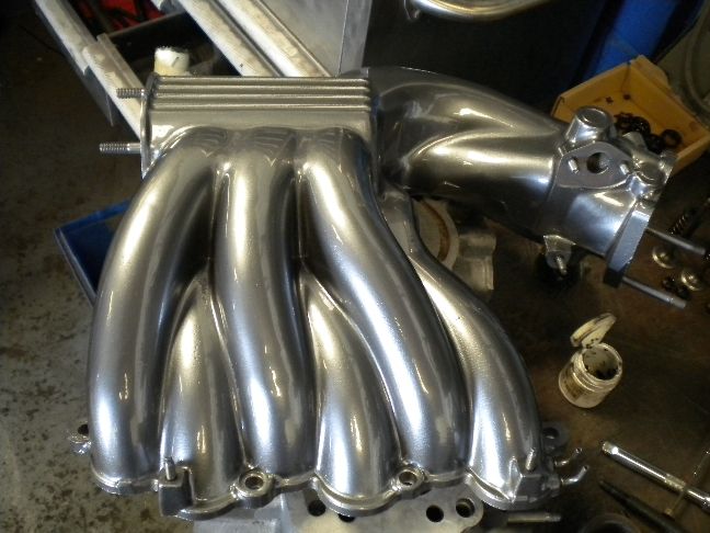
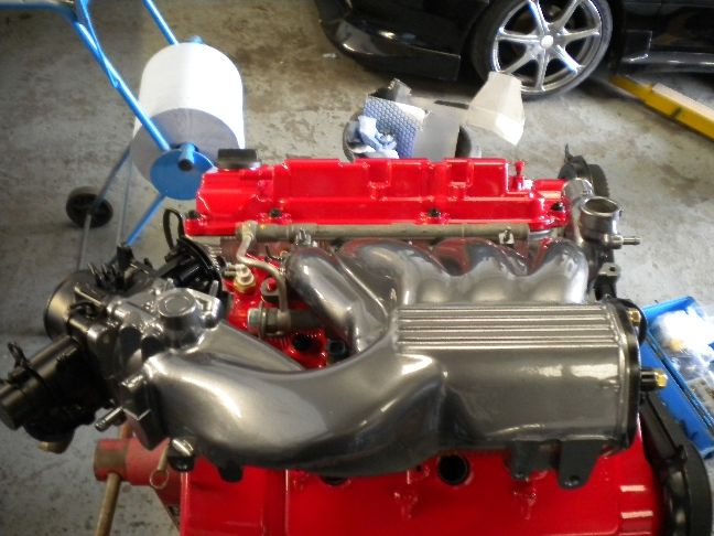
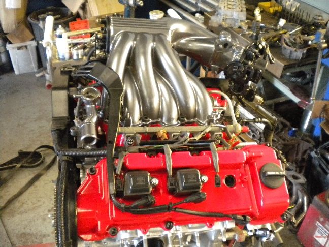
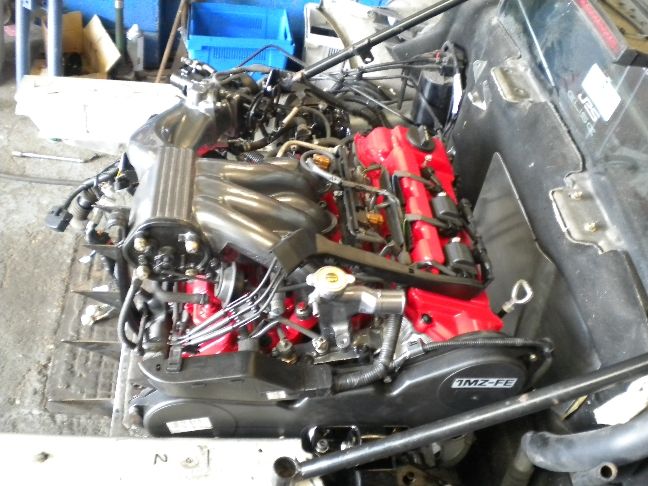
Plenum and throttle body fitted....
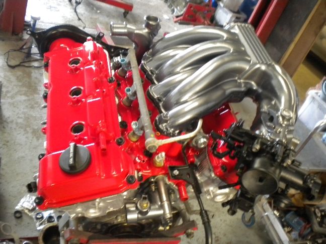
Engine harness refitted...
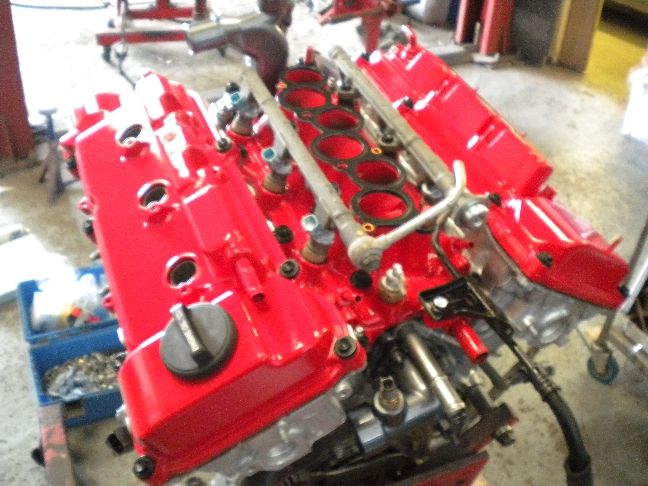
Some detailing...
Almost complete, we leave one coilpack out for engine fitting, it comes close to the lifting chains and risks getting damaged, so we leave it out until the engine's fitted.
Mega update over, i'm off for a pint.
UPDATE 16/6/11
Well not a lot to report on today due to the huge amount of work done yesterday, most of today has been taken up with smoothing engine brackets and seam welding my tacked fabricated parts, not really worthy of pics to be honest.
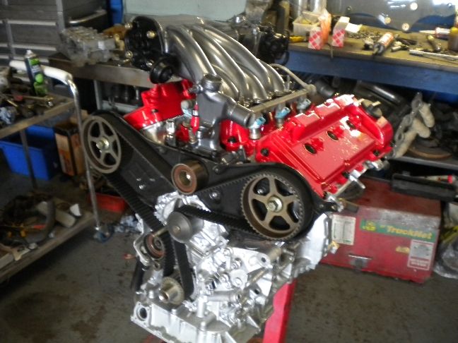
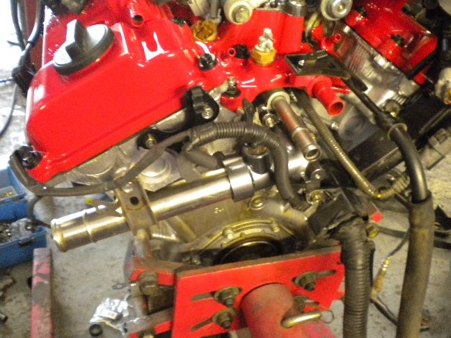
However i have now finished the engine detailing 100%, the timing cover, crank pulley and various other parts are now done...
Also made an EGR blanking plate, we don't allow EGR on our builds, it's horrible and cokes up engines very badly, makes idle speed controllers gunk up, plus raises intake temps and well.... i just hate it, so it goes.
The engine as it stands now, just needs it's plastic top cover doing which covers the electricals you can see in front of the plenum.
UPDATE 17/6/11
No work done at all to the conversion itself today, instead i spent the day making jigs of every fabricated part i've had to make, these make this conversion instantly repeatable without having to hang the engine to make stuff, which in reality will save around 2-3 weeks work.
Sorry it's not an exciting update but the jigs just had to be made.
UPDATE 21/6/11
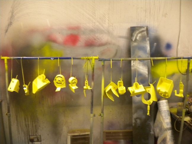
With everything now 100% jigged up for future use i finished prepping all of the parts i've had to make over the last month, everything smoothed off and treated to a high build primer coat, tomorrow these will all be gloss black.
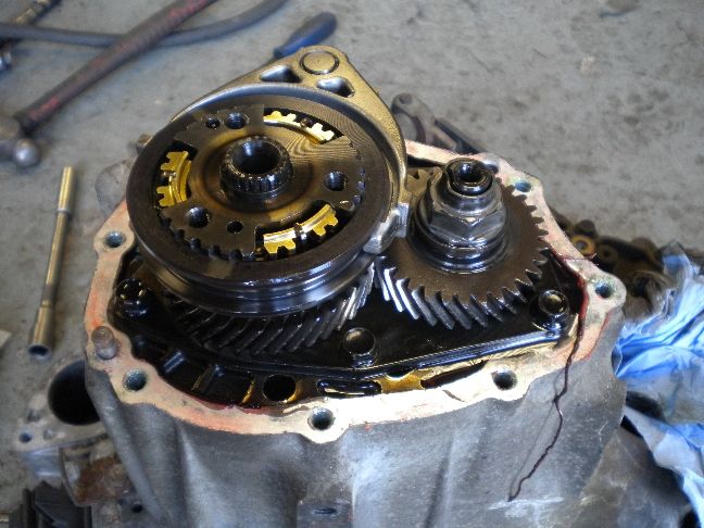
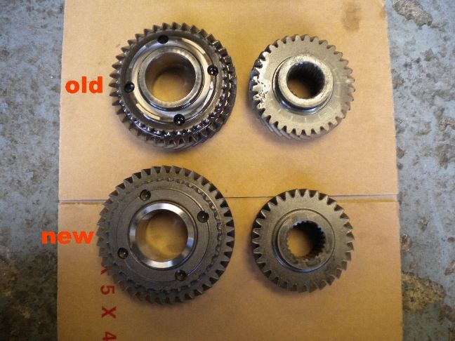
While those were drying i started work on the gearbox, the best box to use with the 1mz is the Celica NA unit, but even then we find its 5th gear a little short. It's the same story on the Mr2 conversions, we have this very rapid 1st through 4th acceleration and the stock 5th just tops out too early, and equates to 4000rpm at 80mph on the motorway, which we have always found a little on the high side. After all if you have a V6 you want to be able to snick it into 5th on the motorway and cruise.
So a few years ago we discovered a 5th gear set from the Avensis Diesel was a direct swap into the Mr2 and Celica gearbox, this discovery took over a month of research to find, and many pairs of wrong 5th gears bought until i found the correct ones, but since making this discovery just about every V6 conversion we do these days gets the extended 5th gear pair fitted during the conversion.
This new 5th set brings the 80mph cruising revs down to 3200rpm which is much more like it.
I will be fitting these gears to every Elise conversion within the turnkey price as standard, for us it's a "must have" mod.
Here is the old 5th set...
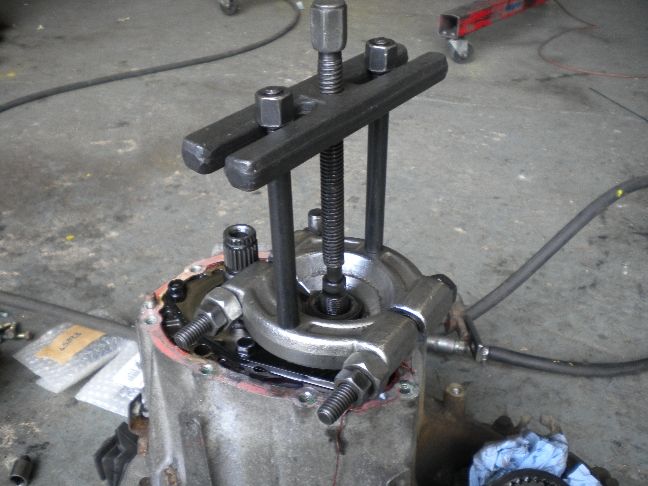
I made a tool years ago to remove the synchro hub without breaking anything, priceless to me now...
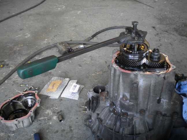
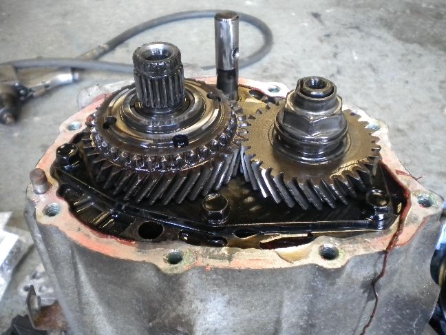
With the selector fork and synchro hub off we are left with the 5th gear pair, the mainshaft gear just lifts off by hand at this point....
The layshaft 5th needs a puller to remove it....
Here is a shot of both sets of 5th's, you can see the difference. The stock 5th pair is 0.82:1 , the new 5th pair is 0.73:1
The gears all fitted and synchro hub refitted...
You got to know what you're doing inside these Toyota gearboxes, many mistakes are made by amateurs leaving the gearbox wrecked first drive!
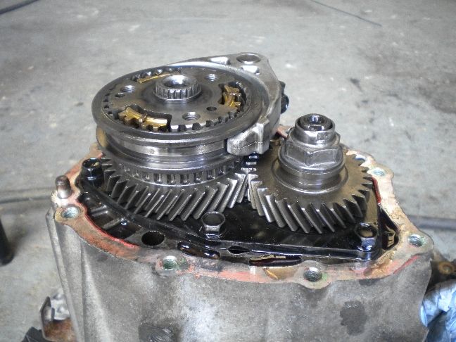
The gearbox now needs a thorough clean and will be primed and painted, then new driveshaft oil seals fitted before assembly.
Here are my top secret sauce driveshafts! A nice supported shaft setup, the supported shaft itself is NA Celica, the rest is...... ah that would be telling! :p
I am aiming for final assembly of everything back into the bay by the end of this week. I keep getting asked if what you see in this build is just for the first one, so just to recap, everything you see being done on this build gets done on every build we do.
UPDATE 22/6/11
Today saw the custom parts painted, these will never rust now.
The rest of the day was spent making an exhaust jig, so the downpipes can be replicated off the car saving us a lot of time in future... excuse the state of that metalwork bench, it's been a long week of jig making!
UPDATE 23/6/11
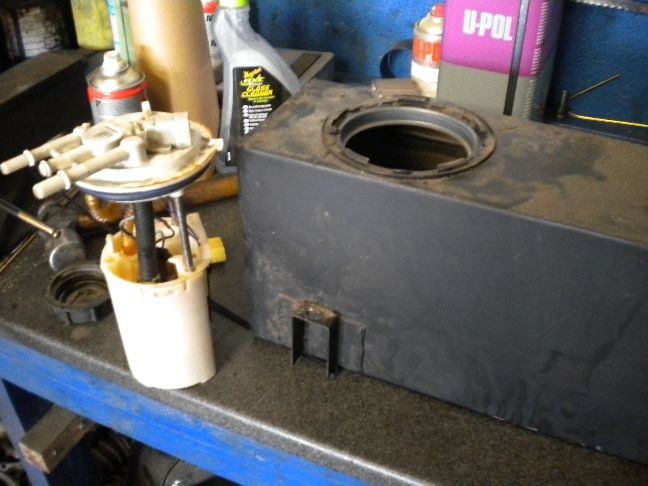
Today i decided to drop the fuel tank out and replace the pump, i have no idea what BHP the K series pump is good for so i decided not to take any chances and replace it with the Camry V6 pump which is obviously made for the job.
The tank came out a lot easier than it does on an Mr2 and the V6 pump installed with very little modification...
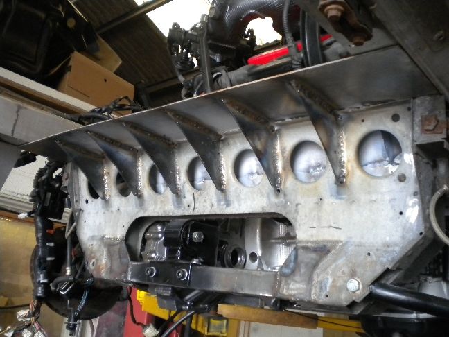
I spent the rest of the day working on the subframe, which i know has been a sore point with some owners, but it's as simple as this, if it wasn't modified then a V6 just wasn't going to fit, i'm not Jesus, i can't miracle space from nothing, although i do own a rather nice pair of sandals.
So the first step was to box the face back in that i had removed for engine clearance, now please don't pre-judge here, there is still a LONG way to go, this is just the next stage in beefing up the subframe, i have about 3 or 4 more things i'm going to do before i even think about the detailing and rust protection, anyway here is the front face boxed in...
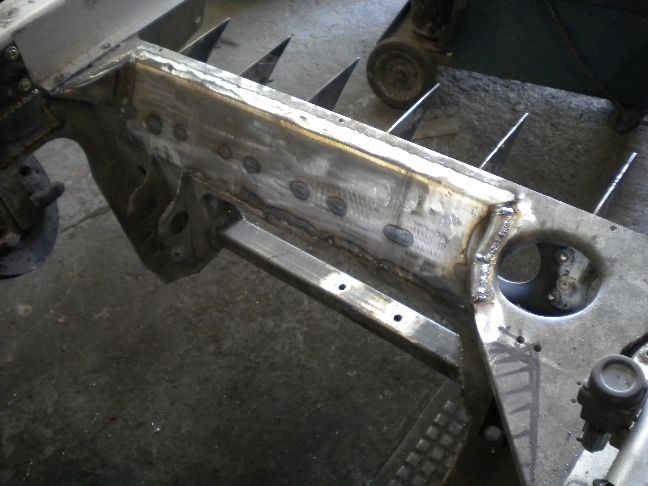
Now i'm obviously very aware that even boxing it back in may not make it as strong as it was (even though the original was just spot welded everywhere, and i am seam welding the whole thing) so i have decided to add strength to the rear of the subframe and give it a new top section that will tie the whole thing in to be much stronger in my opinion.
The first stage is to add gussets, not the type found in your girls pants.... although if i were cutting corners that might work!
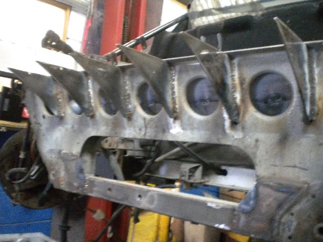
These have been seam welded both sides, the welds are surprisingly good considering the galvanizing (which i've removed best i can pre weld)
A new top face will be added on these gussets and extend forward over the top of my cut section as far as i can, so by the time it's finished there should be more strength in this by miles.
So that's stage two of the subframe mods, lots more to come on this as i know people are concerned about it.
UPDATE 24/6/11
Not a lot of progress today, i had to catch up on other things in the workshop with the Elise taking up so much time, but i did get the gearbox cleaned, etch primed, hi-build primered, basecoated with my own mix of gunmetal (same colour as the plenum chamber) and clearcoat laquer applied...
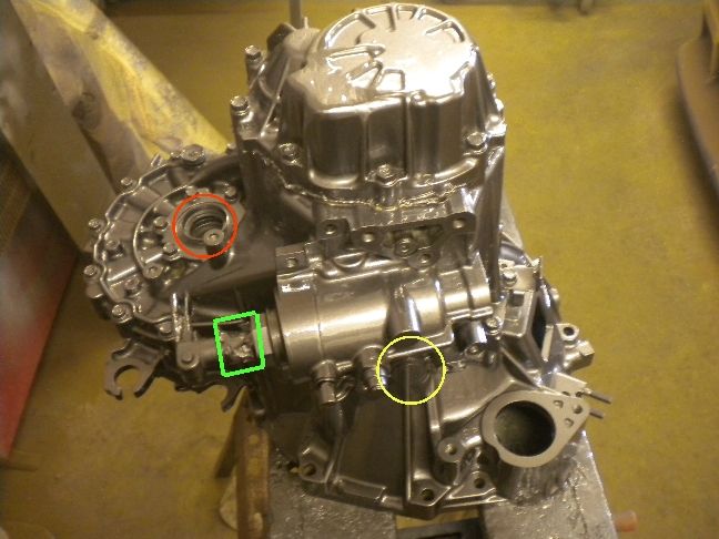
RED circle, i have left the old driveshaft oil seals in for now, they are covered in paint, but new ones from Toyota are on the way, just so you know i don't just paint over seals.
GREEN square, the selector shaft rubber boot has been removed and i have masked the shaft itself, so no paint goes on the important areas.
YELLOW circle, the reverse light switch has been removed prior to painting, last thing i want is paint on electrical connections.
Monday sees gearbox meet engine and the whole thing installed back in the bay, i need it back in to finish subframe mods and there really is no reason for it to stay out now. Work will progress at an accelerated rate now, i expect to be starting wiring by midweek and if everything goes to plan a startup video by next weekend. The following week will be clam and engine cover work and final finishing off, so a fortnight should see this done now.
UPDATE 27/6/11
Ok this is when stuff starts to look like it has been worth the effort, putting all of the pretty parts together is the best bit!
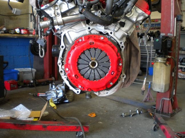
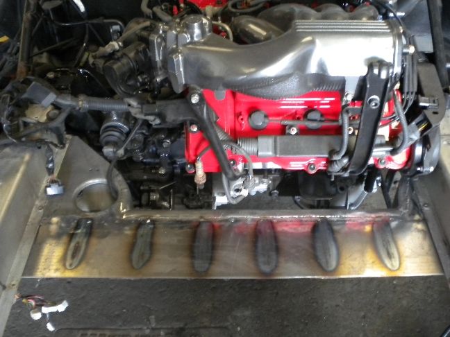
I started by fitting the new clutch assembly, a 6 paddle uprated one that will feel good without being overly harsh and will take some abuse, every conversion will come with one of these as part of the package, these have been well proven on the Mr2's.
Next job was fitting a better heatshield to the front firewall than the stock tinfoil, 2mm sheet used here bent and cut to shape, much better.
With the gearbox bolted to the engine it was time to rehang it permanently with its fresh engine mounts.
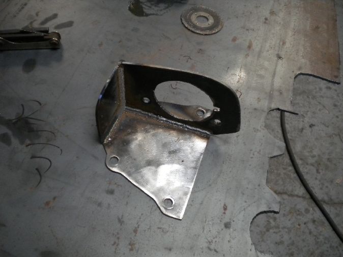
Rear axle shaft carrier bracket, the one i made ages ago...
Tomorrow will see everything hooked back up and i can get the exhaust downpipes finished.
UPDATE 28/6/11
Not a lot done today as there was other vital work that needed doing elsewhere in the garage, "one of those days".
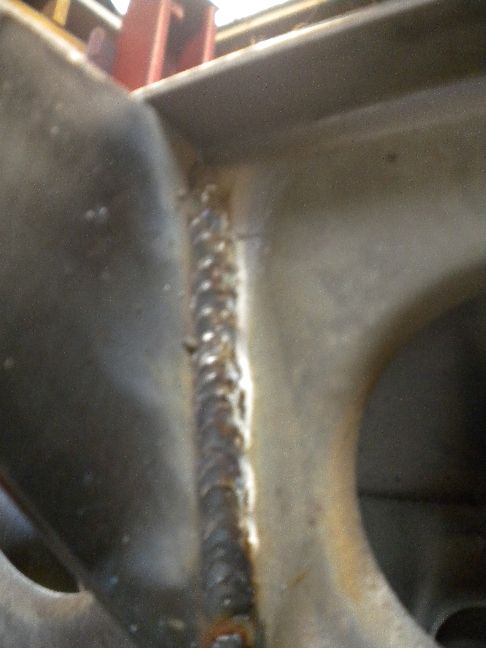
Come 4pm i was able to drop back onto the Elise and i got stage 2 of the subframe strengthening finished by adding the top section.
This has been seam welded along the top edge to the old subframe and seam welded to both sides of the gussets, it's extremely strong now, i feel i really have replaced more than any strength that was lost by modifying the engine side of it.
I'm still not finished though, there is more to come on beefing this up, you guys said it was a major concern so i'm throwing a lot of time into making this as good as it can be.
Excellent penetration..... ooh matron etc...
I can also tie this new top section into the outriggers with speed bolts.
UPDATE 29/6/11
Loads of progress today, first job was to fit the new driveshaft oil seals....
Then the driveshafts went on, i also gave the lower wishbones a refurb, they weren't in good health cosmetically.
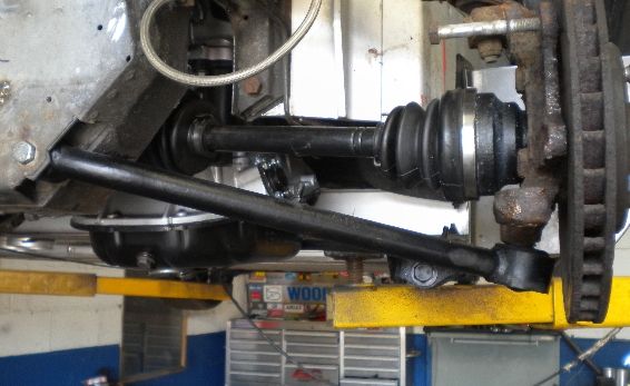
A pic of the supported shaft running through the bracket we made, this support bracket has been well tested over the last 5 years on the Mr2 swaps.
Viewed from the rear you can see how parallel the shaft runs to the rear member, the hours of mm perfect engine alignment paid off.
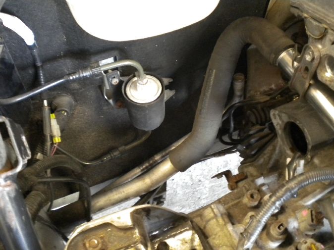
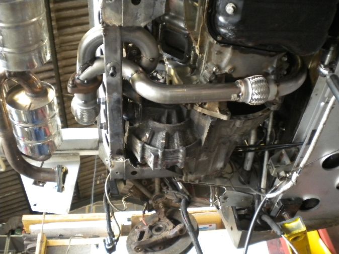
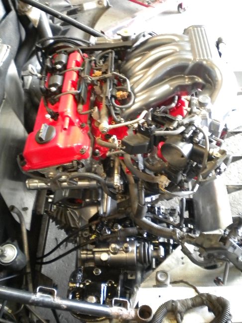
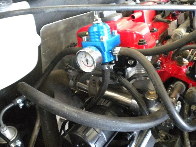
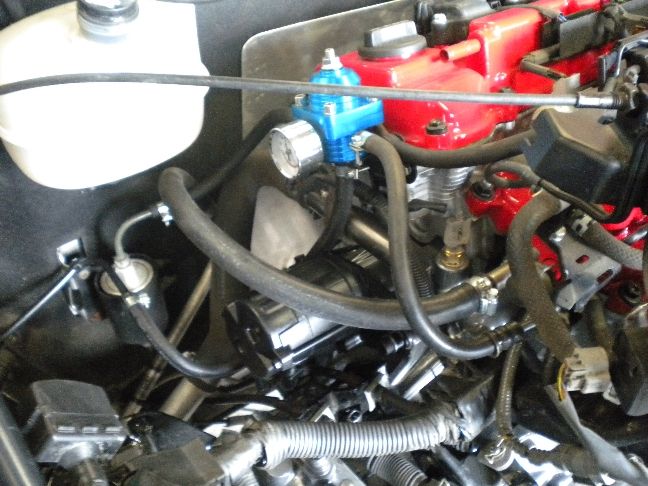
All radiator pipes were refitted, i made those during the fabrication stage, heater line installed and the fuel pipework sorted. I am using an aftermarket FPR, we need to do this with the 1mz as it has no return type rails, both the Mr2 and the Elise use a return style fuel system so the regulator is dual function, it lets us return fuel to the tank and also regulates pressure.
Starter motor is also fitted, most wiring routed, ignition amplifier mounted and alternator hung.
I've mocked up the air filter location, this is the customers old induction kit which he wanted to retain, and has its own cold ram air feed which sits in the NS vent.
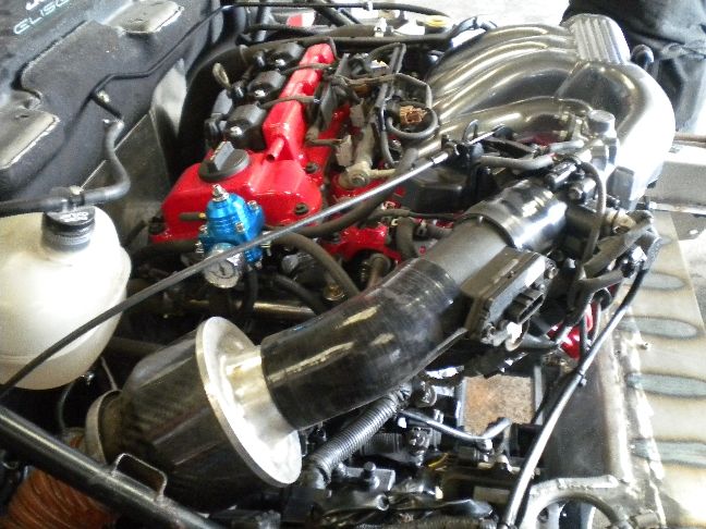
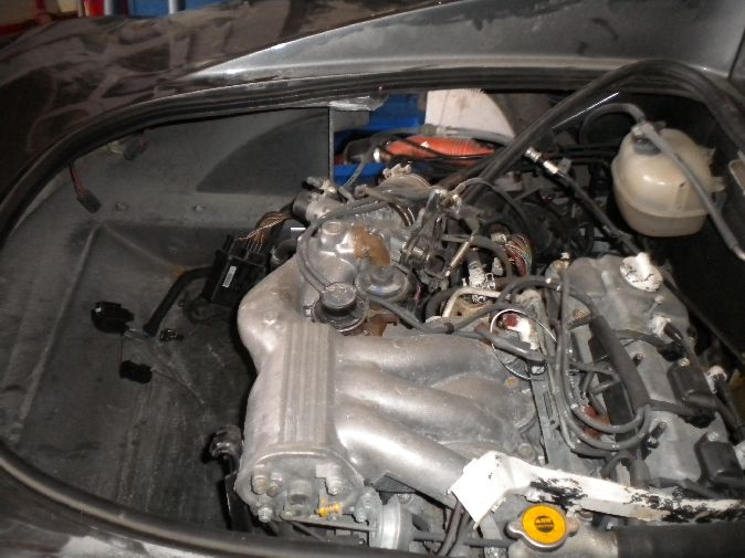
So it's now 100% plumbed in, just the exhaust to do tomorrow and i can start wiring up. There is more work to do to the subframe and clam/engine lid too but here is an overview as it stands now.
UPDATE 30/6/11
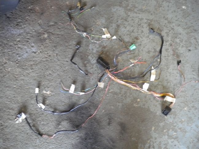
Today saw the start of wiring up and more work on the boot wall divider. I stripped down the K series loom so that i could identify and label everything, this is done alongside reading the circuit diagrams, i like to double check everything because diagrams can change month to month and a small revision to something can catch you out, i find this a much more methodical way of working, spaghetti is a favourite job of mine, the harder the better!
Here is the K engine loom taken back to the bare essentials, i may end up only using a few of these plugs eventually...
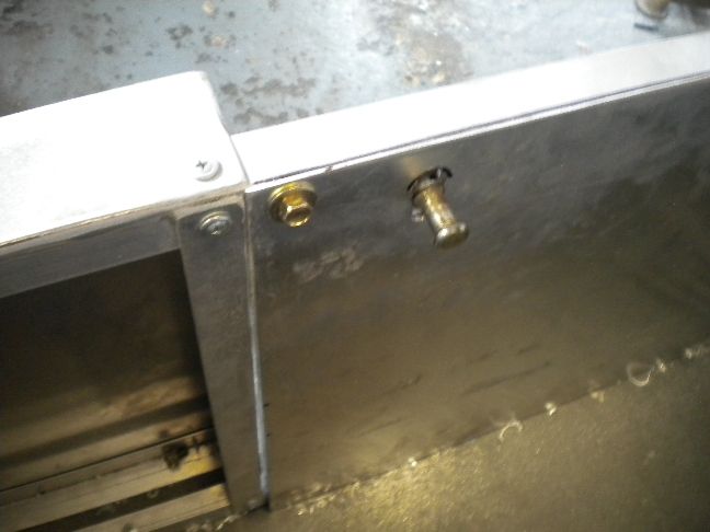
Here is the 1mz Camry immobiliser system, it has its own ECU, pickup coil/transponder and the original Camry key, this will all be hardwired into the Camry ECU so that it is permanently disabled, although it would still be possible to detach any part of it to completely immobilize the car if you went on holiday etc...
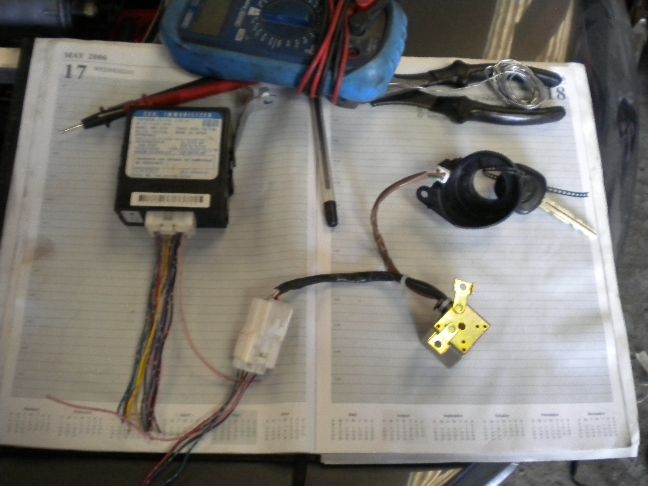
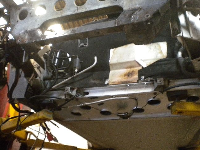
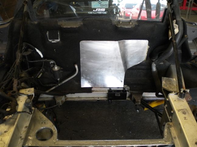
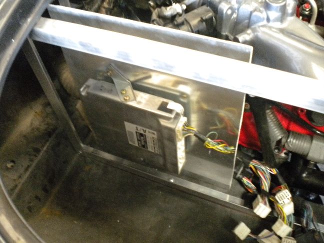
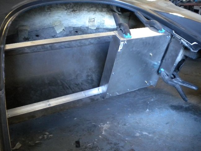
I have also started work on mounting the 1mz ECU, now these are not an "all weather" type ECU, the plugs and connections (and the ECU itself) are not waterproof and it needs sealing away from the elements. So i am making its very own cubby box that will be sealed from any moisture. It will have a removable access panel from the boot side. If i end up needing to keep the original K series ECU for dash functions (unknown as yet) then that will be mounted in its original position on the other side of this wall.
I've started filling the cooling system, we like to get coolant down their necks as early as possible.
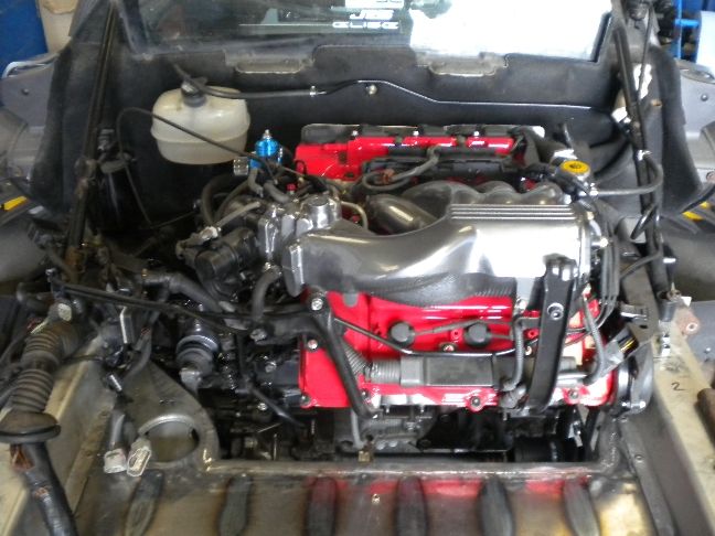
An overview of the install as it is now, there is still a surprising amount of work to do even at this stage.
UPDATE 4/7/11
Another day of intensive wiring done, i'd say it's 50% wired now, most of the time being spent is research and triple checking, but it's getting there. So far the ECU is powered up, Injectors and coilpacks powered, the oil pressure signal done, CEL done, immobiliser wired in, OBD2 socket wired in, and fuel pump relay and engine main relay both being controlled by the new 1mz ECU.
Tomorrow will see the starting and charging circuits completed along with speedo, tacho and coolant temp.
Today i had a slight problem with the alternator belt, for some reason it was just fouling the Elise engine mount bracket on the chassis, i was 100% sure i double checked this when dummy hanging the engine, but anyhow when i came to fit the new belt it was fouling by about 5mm.
Now the easy answer is to whip the grinder out and shave 5mm from the area in question, but i started this build with a determination not to touch the stock chassis brackets in any way, so instead i made an idler assembly from scratch....
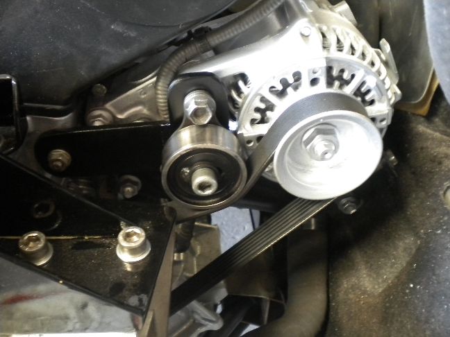
This diverts the belt away from the chassis bracket and is a very easy way to solve the problem.
UPDATE 5/7/11
Wiring now 100% completed, tomorrow is start up day.
UPDATE 6/7/11
It's alive! The worlds first 1mz powered Elise is running. It actually fired first turn of the key but i did spend the rest of the day hunting down a strange wiring issue, basically the engine wouldn't shut down when i turned the ignition off!
It took me almost 7 hours to trace the fault to an ignition wire that was picking up a residual stored current from a VSV which was holding the engine main relay latched which in turn was keeping the thing alive. The main thing is i found the issue and apart from that all is well.
As a result of spending all day hunting that glitch i didn't get a start up video, that will come tomorrow now that i have everything sorted.
My first fire up was also with the rear silencer left off, i had planned to fit that as soon as the first test firing went successfully, so i don't even know myself yet what it truly sounds like, but it's bloody loud just running on its downpipes.
Guaranteed video tomorrow.
UPDATE 7/7/11
Here is video of it running, not the best audio quality, my mic tends to get drowned out by the V6, and it picks up valvetrain noise that isn't present in person.
Also a quick check on the scanner that everything is working as it should be, and it is. All dashboard functions work and we have no issues electrically.
We did find the radiator struggling to keep the temps down during long idling periods, definately suffering from heatsoak and clearly not up to the job, so we are fitting a much more efficient alloy rad next week to take care of this.
The exhaust note sound so much nicer in person but you should get some idea....
http://www.youtube.com/watch?v=08r6eGiWPr8
UPDATE 20/7/11
The new alloy radiator has arrived and was fitted today, took a bit of figuring out how to remove the front clam, it was my first one, but the next one will remove a lot quicker. Kev we found a dead bird inside your clam, looked like it got caught in the vent at some point!
I am now working on the rear clam bodywork and the engine lid, so i'll post up pics of that when done, then we can finally get the car off the lift and start driving it.
Thanks Paul.
UPDATE 26/7/11
The new radiator has totally solved the slow heatsoak issue we were having, so we were correct all along, the Elise rad just cannot cope with the V6. With the new rad fitted we held 93* for 10 minutes before the fan cut in, the temp rose to 94* then settled back to 91* (all of these temps are at the engine, not the rad), this cycle repeated endlessly for as long as we wanted and at 900rpm.
On raising the RPM to around 4000rpm for a sustained period (bearing in mind no airflow through the rad whatsoever), the temp rose to 96* but the fan always dragged it back down to 92*. The 1mz coolant temp switch operates at 93*. The above tells us there is just not enough efficiency in the stock rad to cope with a bigger engine.
I am also going to fit a secondary fan so that the Elise fan is doing less duty and safeguard against any heatsoak it might see on track, i really don't think the second fan is necessary but i'm going to fit it anyway.
Also today we fitted a Dakota unit to modify the tach signal, it was over reading so the Dakota unit (which we have used many times before) sorts that out.
I am still working on the rear clam but as soon as that is complete we can rebuild the rest of the car and drive it for the first time.
UPDATE 27/7/11
Work has continued on the subframe adding more strength everywhere i can, i already know the amount of structural strength i have added is way more than the small amount originally removed, but i'll keep adding it anyway. Today i added triangulation plates to the underside of the subframe, i have also boxed in the area above the driveshafts which is now redundant on this car, so that is helping tie the subframe into the chassis attachment point better than it was previously.
I have some more brace bars being made tomorrow that will run from the bottom corner of the subframe onto the front chassis rail and i'm very confident now that this is more than strong enough.
We fitted the new swanky rear track rods today, Kev will be able to tell you the make if you wish to know.
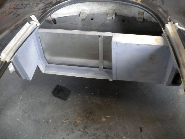
Work is also progressing nicely on the clam, the weatherproof box for the ECU and all other electrics is now finished, i just need to dress this off and prime/paint, then make two removable panels, one for the ECU box and the other for engine bay access to get at the rear bank of spark plugs when need be. I also need to repair the clam with fibreglass where the original boot wall was removed, but it should all look meant to be when finished.
I've definately well underestimated the amount of work this has taken so far, but i will be keeping to budget regardless, such is the nature of a first time build like this, the next one will be so much quicker and easier.
UPDATE 28/7/11
Today saw the extra radiator fan fitted, which is not strictly needed, i prefer to think of it as a safety measure just in case the single fan struggles on a red hot track day etc, better safe than sorry.
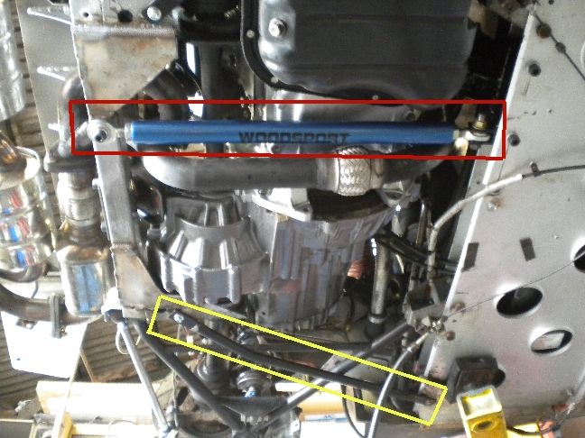
I got the Woodsport torque bar refitted, that's it boxed in RED , this should really help the rear subframe out, in my opinion the subframe lacks rigidity at its base, the only thing tieing that into the car are the lower wishbones and they still are, but i feel this beefy bar we have added will just give it some more where it needs it, this should also translate any rear torque mount downward force into the front crossmember, or at least help.
I also made two other braces YELLOW that run from the lower corners of the subframe to the front crossmember, these are lighter by design and will hopefully help.
So we are almost there now, just the car to refit now, both clams back on and it can be driven for the first time.
UPDATE 1/8/11
The new brakes are all fitted now, more of an update for Kev there than a swap update! The front clam is refitted and the final works are being done to the rear clam before that can be refitted for the final time.
The clutch has now been bled and works perfectly, it has a nice light action and feels very similar to our Mr2 pedal with the same conversion.
I have also found a way to retain the boot lock, it has been moved rearward by about 6" and a new catch assembly made, the lid will need repainting which will be the final job on the project. I think we are down to the final week of this now, it's been a marathon build but the results should speak for themselves.
UPDATE 3/8/11
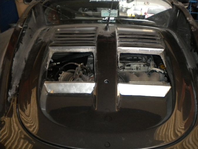
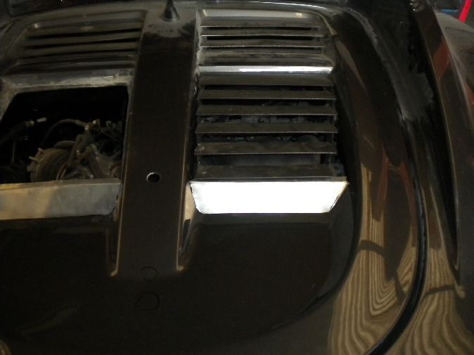
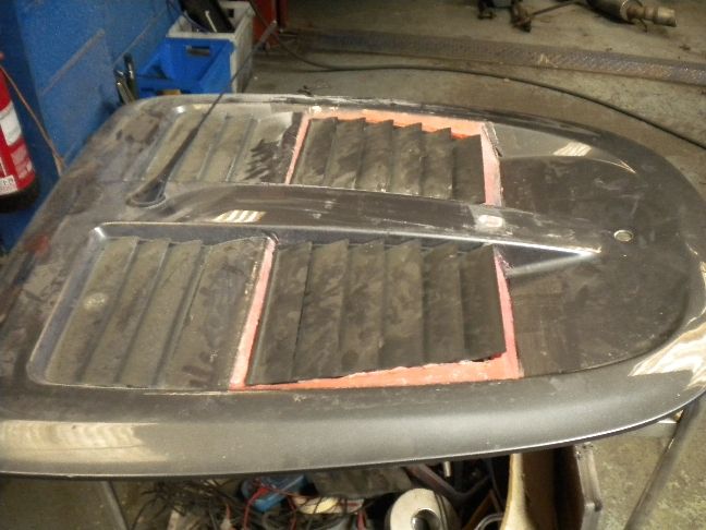
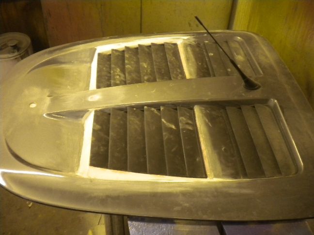
The final stage of works is now being carried out on the rear clam and engine lid. As you may recall the lid needs the rearmost vents raising to clear the V6 plenum chamber, either that or a completely different lid or a massive redesign, but we opted for an OEM look and by the time it is finished it should look pretty factory. As always you get to see the bare bones fabrication stage, and all stages in between until the final paint goes on.
This is the raw fibral 1st build up stage just getting a basic structure in place to work from...
There are quite a few hours work in this to get it right, the keener eyed will already have spotted the relocated lock assembly some 8" further back...
This latches onto the new striker which is bolted to the new boot wall...
Work is also progressing well on the clam, i'm just about finished here with just paint to add, the rain channel sections have also been repaired where i cut the original boot wall out, so it looks seamless now...
Things are going to get a lot dustier looking as the heavy sanding begins, but all necessary to get the desired finish.
UPDATE 4/8/11
Work progressed on the engine lid, more shaping and profiling work and i now have the vents raised and sitting where i need them to be. This should look almost OEM when painted to the untrained eye.
You can follow the last part of this project here http://www.scottishelises.com/phpbb/vie ... &start=300